
Permanent Magnetic Couplings: Synchronous Torque Sizing, Containment Can Eddy Losses, and OEM Sourcing Guardrails
Size permanent magnetic couplings with torque examples, containment can loss checks and NdFeB grade guardrails. Use the OEM RFQ checklist to request a review.
Permanent magnetic couplings transmit torque between driving and driven rotors without shaft-to-shaft contact. In a hermetic drive, a stationary containment can separates the process fluid from the atmosphere, removing the dynamic shaft seal at that boundary. The complete assembly still needs qualified static seals, pressure integrity and fluid-compatible materials.
For OEM engineers and buyers, three questions determine whether a custom NdFeB coupling is a viable candidate:
- Will it remain synchronous at the hottest operating condition? Compare hot pull-out torque with process torque, starting resistance and acceleration demand.
- Where does the loss heat go? A stationary metallic containment can experiences a changing magnetic field even when both rotors turn synchronously. Require a shell-loss estimate and cooling assessment at the specified speed.
- What happens after overload? Define slip detection, shutdown and coast-down behavior before accepting a magnet grade or protection setting.
Reviewed: November 2, 2026. Scope: Global OEM sourcing of custom sintered NdFeB synchronous couplings, with the calculations below limited to coaxial radial-flux arrangements. Face-to-face axial couplings need a different torque integration; asynchronous eddy-current drives need slip to transmit torque and are outside scope. API 685 or ASME B73.3 may be contract requirements for particular pumps; their applicability and edition must be agreed with the pump OEM. This is a screening and RFQ guide, not a compliance assessment or a tested product rating. Numerical examples are hypothetical and reproducible, not measured supplier or customer results.
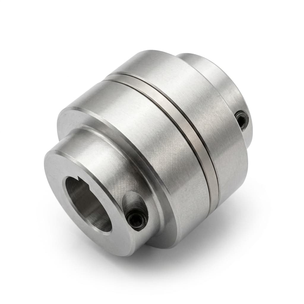
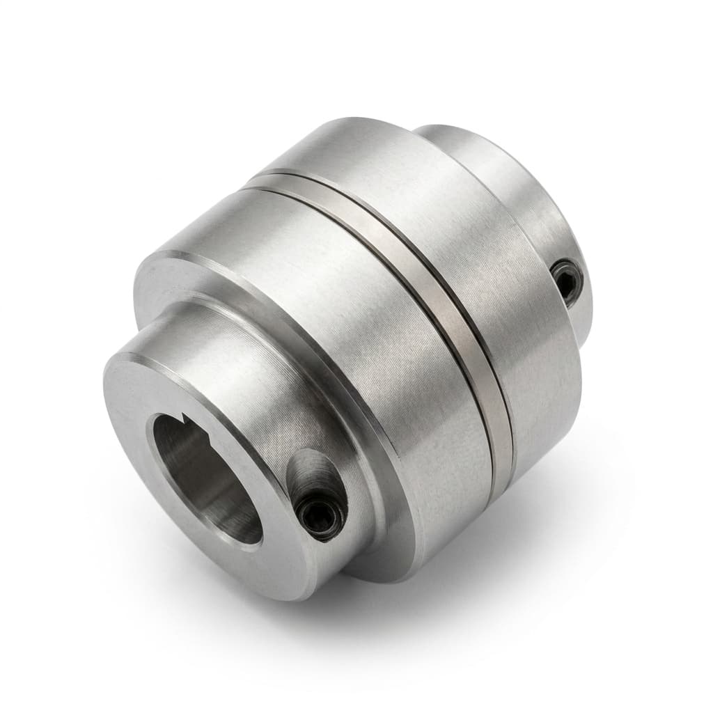
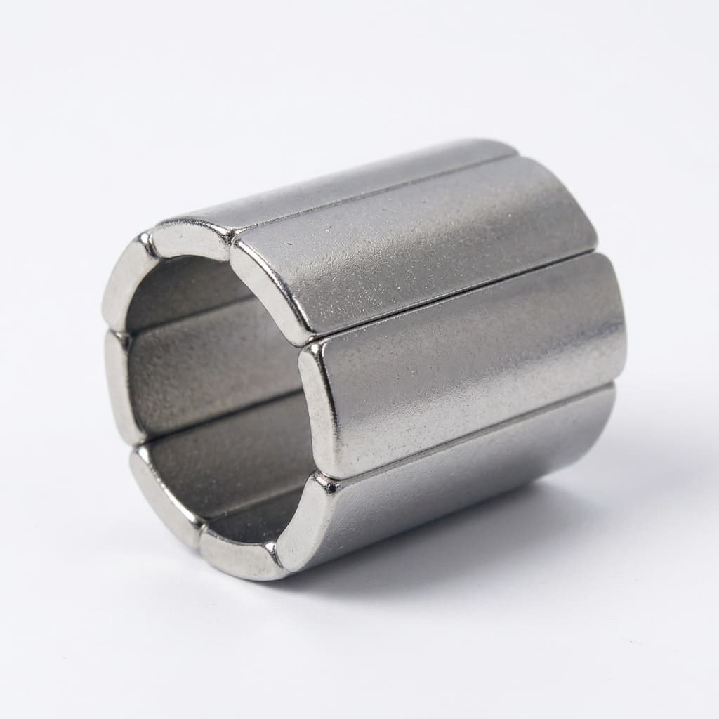
Product illustration only. The exterior does not establish internal construction, encapsulation, pressure rating or tested torque.
To scope a custom rotor program, contact our engineering team with the torque, speed, temperature and fluid envelope, or browse our custom NdFeB magnet shapes.
1. Electromagnetic Principles: Synchronous Torque and Air-Gap Scaling
A coaxial synchronous coupling has an outer driving rotor and an inner driven rotor with alternating permanent magnet poles and magnetic return paths. In steady operation their speeds match. Load introduces an angular displacement between the two pole patterns. For an approximately sinusoidal torque-angle characteristic:
T(θ_m) ≈ T_po × sin(p × θ_m)
Here p is pole-pair count, θ_m is mechanical displacement and T_po is pull-out torque at the stated temperature, gap and axial position. Harmonics and saturation can change the curve; request a calculated or measured torque-angle trace rather than assuming an ideal sine.
Maxwell Magnetic Shear Stress and Pull-Out Torque
Magnetic shear stress in the gap is τ_t = B_rad × B_tan / μ₀, where the two field terms are radial and tangential components, and μ₀ ≈ 4π × 10⁻⁷ H/m. For a cylindrical control surface with negligible axial variation:
T ≈ 2π × R_g² × L_eff × <τ_t>
R_g is gap radius in meters, L_eff is active length in meters and <τ_t> is the circumferential average stress in pascals at the specified load angle. Pull-out torque is the maximum of the resulting torque-angle curve. Multiplying the local peak stress by the entire surface area would overstate torque. This scaling relation does not supply a universal stress rating for NdFeB assemblies.
Worked Sizing Example: Convert Shaft Power into Hot Torque Demand
Assume the driven equipment needs 7.5 kW of shaft power at 1,450 rpm. Use shaft input demand, not hydraulic output power alone; pump efficiency must be included if starting from hydraulic duty.
T_run = 9550 × P_shaft(kW) / n(rpm) = 9550 × 7.5 / 1450 = 49.4 N·m
Suppose the process resisting torque during startup is 70 N·m, excluding acceleration, and driven inertia is 0.08 kg·m². A linear ramp from rest to 1,450 rpm in 1.5 s gives:
T_accel = J × Δω / Δt = 0.08 × (2π × 1450 / 60) / 1.5 = 8.1 N·m
Peak startup demand is then 70 + 8.1 = 78.1 N·m. An illustrative, project-selected margin of 1.4 gives 78.1 × 1.4 = 109.3 N·m, or a screening target of approximately 110 N·m hot pull-out torque. The factor is not asserted as an API requirement. Check other duty points, motor acceleration capability, transient loads and protection behavior before setting the contractual minimum. Add can losses and other parasitic loads to the motor power balance at their actual location; do not count them twice in driven-shaft torque.
A room-temperature pull-out figure cannot establish this hot target. If both rotors' effective magnetic fields fell to 90% of their reference values and geometry stayed unchanged, the simplified field-product model would predict 0.9 × 0.9 = 0.81 of reference torque. This sensitivity example does not replace hot B-H curves, thermal analysis or testing.
The Penalty of the Magnetic Air Gap
The magnet-face separation must include every nonmagnetic layer:
g_mag = c_inner + t_encap + t_can + c_outer
For example, 1.2 + 0.6 + 1.2 + 1.5 = 4.5 mm. These are illustrative dimensions, not required minimum clearances. Adhesive, coatings and other sleeves must also be included where present. The released stack must allow for runout, bearing wear, pressure deflection, thermal expansion and the required fluid circulation.
A simple spatial-harmonic model gives B_g1 ∝ exp(-k × g_mag), with k = p / R_g. It explains why adding pole pairs can hurt field transmission across a large gap. It cannot determine an optimum pole count by itself: compare complete designs at the same envelope, temperature, tolerances and loss limits using electromagnetic analysis.
2. Structural Architecture: Coaxial Rotor Interaction
The schematic shows the layers across an unwrapped radial stack. It is not a literal shaft cross-section or a pressure-boundary drawing. Eddy-current loops apply to the illustrated conductive stationary shell; the drawn clearances and sleeve thickness are examples. Scroll the diagram horizontally on narrow screens; the gap stack and heat mechanism are also explained in the surrounding text.
Coaxial Coupling: Unwrapped Radial Stack (Not to Scale)
3. Containment Can Eddy Losses: Physics and Material Selection
The stationary containment can separates the driven process volume from the outer drive. A rotating pole pattern passes the can at electrical frequency:
f_can = p × n_rpm / 60
For eight pole pairs at 1,450 rpm this is 193.3 Hz, even with zero rotor-to-rotor slip. Frequency alone does not determine loss. Field harmonics, can geometry, conductivity, end-current paths, temperature and the coupled electromagnetic response all matter.
What to Request Instead of a Universal Eddy-Loss Formula
The Joule-loss calculation integrates local current density over the conductive shell volume:
P_shell = ∫_V ρ_e × |J_eddy|² dV
Here electrical resistivity ρ_e is in Ω·m, induced current density J_eddy is in A/m² and volume is in m³, giving watts. The current distribution must come from an applicable analytical model or electromagnetic simulation. Include a time average when the fields vary over a cycle.
Do not apply a universal wall-thickness-cubed rule to a cylindrical containment can. A thin-lamination formula has different field orientation and current paths. Increasing wall thickness can both change current paths and widen the magnetic gap. Likewise, speed-squared and inverse-resistivity trends are only screening approximations when field distribution and geometry remain comparable, with negligible skin and reaction-field effects.
Require the supplier to report watts at rated and maximum speed, material resistivity at temperature, actual wall geometry, model assumptions and validation method. Separate stationary-can loss from losses in rotor sleeves, magnets, bearings and fluid drag. Check internal circulation, fluid vapor-pressure margin and the hottest magnet temperature; an electrically insulating can does not eliminate other heat sources.
For nickel-alloy sheet procurement, ASTM B575-17 includes UNS N10276 among its covered alloys. It is a material specification, not a containment-shell pressure rating or an eddy-loss model. The linked edition is historical; agree the required edition and product form in the purchase order.
4. Containment Can Material Decision Matrix
Use this six-option matrix to request comparable evidence. Pressure and temperature limits belong to the finished can design, joints and service conditions, not to a material name alone. No row establishes chemical compatibility or a universal pressure limit.
| Can material | Eddy-loss consideration | Potential reason to shortlist | Main sourcing limitation | Evidence required before selection |
|---|---|---|---|---|
| Hastelloy C-276 / UNS N10276 | Conductive; model loss using the specified alloy at temperature | Nickel-alloy option for compatible corrosive service | Alloy cost, forming, weld condition and required wall thickness | Material certificate, fluid-specific compatibility review, weld qualification and shell-loss calculation |
| Titanium alloy, exact grade specified | Conductive; do not interchange Grade 2 and Grade 5 property data | Candidate where weight and fluid compatibility support its use | Grade-specific corrosion behavior, joining and fabrication cost | Exact grade/product form, temperature-dependent properties and pressure-boundary qualification |
| Austenitic stainless 316L | Conductive; include actual wall geometry and material condition | Established forming and welding supply chain | Fluid compatibility and thermal budget can rule it out | Corrosion assessment for actual concentration/temperature, material certificate and calculated loss |
| Carbon-fiber reinforced PEEK | Carbon fibers can form conductive paths; do not assume zero eddy loss | Composite construction where a qualified design offers an advantage | Anisotropic conductivity, creep, permeation, layup and joints | Actual composite conductivity, layup, long-term pressure/temperature data and chemical compatibility |
| Zirconia ceramic | An electrically insulating grade can suppress shell eddy currents | Candidate when metallic-shell heating is limiting | Brittle fracture, joining, thermal gradients and pressure transients | Exact ceramic grade, proof-test plan, joint design and thermal/mechanical shock qualification |
| Silicon nitride ceramic | Confirm electrical properties for the actual grade and temperature | Candidate where a qualified ceramic design meets thermal and mechanical needs | Cost, grinding, brittle failure and attachment details | Grade data, inspection method, pressure/thermal-cycle tests and attachment validation |
Comparing quotes? Send the duty envelope for an engineering review and ask each candidate supplier to state the same hot torque, loss, pressure and test assumptions. A lower-loss material is useful only if the complete assembly meets the service requirements.
5. Dynamic Slip Demagnetization and Thermal Protection
If load exceeds available pull-out torque, the rotors can lose synchronism. The driven rotor may slow, oscillate or stall; it does not always stop immediately. The relative pole-passing frequency is:
f_slip = p × |n_outer - n_inner| / 60
With the inner rotor locked and eight pole pairs, an outer speed of 1,450 rpm gives 193.3 Hz; at 2,950 rpm it gives 393.3 Hz. These are calculated frequencies, not measured heating rates or damage thresholds.
During slip, reverse fields and additional rotor eddy-current heating can reduce the demagnetization margin. Actual damage depends on magnet geometry, segmentation, temperature, B-H curves, cooling and event duration. There is no universal temperature rise in seconds, percentage of remanence lost or safe trip delay.
Prevention Strategies for OEM Sourcing
- Select grade from the hot operating point. Treat grades such as N38UH or N35EH as candidates, not mandatory solutions. Require supplier-specific demagnetization curves and a check of the worst reverse field at the predicted magnet temperature. An SH label does not automatically fail, and a UH/EH label does not guarantee survival.
- Evaluate manufacturing alternatives with evidence. Grain boundary diffusion may change the coercivity/cost trade-off, but performance depends on part thickness and processing. Our guide to reducing HREE costs via GBD explains what to ask before approving a change.
- Validate protection as a complete system. Define how slip, low flow and overheating are detected. Establish detection delay, drive shutdown and coast-down time from the permitted thermal transient, including sensor coverage and fault conditions. Motor power alone may not reliably distinguish every decoupled state.
A closed discharge valve can cause low-flow heating without exceeding pull-out torque. Address this hydraulic upset separately from a jammed rotor or high-viscosity startup.
6. Inner Rotor Hermetic Encapsulation: Chemical Fluid Isolation
When the inner rotor is wetted by aggressive process fluid, standard nickel plating alone is not a qualified hermetic barrier. A pinhole, damaged edge or incompatible coating can expose NdFeB and compromise the assembly. Specify the actual fluid, concentration, contaminants, temperature, pressure and cleaning cycle before selecting protection.
Engineering Requirements for Encapsulated Rotors
- Barrier material and thickness: Select the sleeve, end closures and joints for the full service envelope. Distinguish the rotating encapsulation sleeve from the stationary containment can; each adds to the magnetic gap and can introduce loss.
- Qualified joining: For a welded design, define penetration, inspection, heat input and protection of the magnets during assembly. Require process qualification on representative geometry rather than prescribing laser welding for every design.
- Leak acceptance: Agree the leak-test method, tracer gas, test pressure, sensitivity, calibrated reference leak, allowable leak rate and production coverage. A test-method standard does not establish one universal acceptance rate. Check whether pressure and thermal cycling must precede the leak test.
- Potting and retention: Require evidence that adhesive or potting, where used, tolerates process temperature, expansion and vacuum conditions without compromising magnet retention. Potting is not a substitute for a qualified wetted-fluid barrier.
7. Dynamic Rotor Balancing and Unbalanced Magnetic Pull
Mechanical unbalance creates speed-dependent loading. Eccentricity between magnetic rotors also changes the circumferential gap and can produce unbalanced magnetic pull. A balance certificate alone does not validate coaxial alignment or magnetic forces.
Evaluate the assembled tolerance stack, bearing deflection and thermal displacement. Request electromagnetic force analysis for the worst permitted eccentricity where bearing load is critical. A single uniform-field formula cannot establish a universal radial load or safe runout limit.
ISO 21940-11 and the Purchase Specification
ISO 21940-11:2016 addresses procedures and tolerances for rotors with rigid behavior. Confirm whether that scope fits the rotor and agree the required balance grade, service speed, correction planes and allowable residual unbalance. Do not infer a universal G2.5 requirement from speed alone.
Balance and inspect in the agreed final assembly condition, including magnet installation, encapsulation and finish machining. Specify runout datums, measuring locations, axial centering and acceptance values from the actual clearance budget. Place balance corrections on designated structural features; do not machine brittle NdFeB blocks as an ad hoc balance correction.
8. Sourcing & Engineering Checklist for Magnetic Coupling RFQs
Provide this checklist with the drawing. The buyer and pump OEM should agree acceptance criteria before comparing quotations:
- 1. Duty and torque: State shaft power, rated/maximum speed, continuous and startup process torque, driven inertia and ramp time. Set a project-specific minimum hot pull-out torque with its margin rationale.
- 2. Thermal envelope: State fluid, ambient and upset temperatures. Require the predicted magnet hot spot, cooling assumptions and the grade-specific hot B-H curves used in the design.
- 3. Pressure boundary: Specify design pressure, vacuum duty, transients, wall geometry, corrosion allowance and applicable code/standard edition. Have the responsible designer define proof and burst criteria; do not use generic multipliers from this guide.
- 4. Cooling and loss: Require the internal circulation path, minimum cooling conditions, loss in watts at each duty point and the fluid vapor-pressure margin. Use the pump OEM's sealless-drive circulation arrangement rather than assuming a mechanical-seal flush plan applies.
- 5. Magnet specification: Record supplier grade, material lot, magnetization pattern, hot coercivity evidence and acceptance method. Require approval before changing chemistry, GBD process or segment geometry.
- 6. Encapsulation: Identify every wetted barrier and joint. Define corrosion evidence, leak-test method, acceptance rate, calibration, sampling or 100% coverage and the required inspection records.
- 7. Gap and clearances: Document encapsulation thickness, can wall and both running clearances, with worst-case runout, pressure deflection, expansion and wear. Include a rub/fault assessment.
- 8. Rotor balance: Agree whether the rotor has rigid behavior, the applicable balancing procedure, grade, speed and correction planes. Require residual-unbalance results and final assembly identification.
- 9. Alignment and retention: Define datums, bore fits, radial runout, axial centering, segment retention and bearing-load limits from the actual drawing and operating envelope.
- 10. Acceptance and change control: Agree ambient and hot torque-angle tests, uncertainty, production sampling and traceability. Validate slip detection and shutdown/coast-down behavior on an approved prototype procedure; a cold static torque test alone is insufficient.
9. Frequently Asked Questions (FAQ)
Why does a magnetic drive pump fail to transmit torque after a restart?
Possible causes include continued mechanical obstruction, insufficient torque at temperature, misalignment, retention damage or irreversible demagnetization after slip. Stop and follow the OEM's fault procedure; check free rotation, alignment and torque capability before diagnosing magnet damage. The magnet's grade suffix alone cannot establish the cause.
How do we choose between a metallic C-276 can and a zirconia can?
Compare complete designs against the same pressure, fluid chemistry, thermal budget and transient loads. A conductive metal can needs a loss and cooling assessment; a ceramic can needs grade-specific pressure, joint and shock qualification. Neither material name establishes code compliance, and there is no universal pressure or speed crossover.
Can we increase coupling torque by replacing N38UH with N52?
Higher room-temperature remanence can increase torque in a comparable magnetic circuit, but N52 is not a drop-in thermal upgrade. Compare supplier-specific hot B-H curves, reverse-field margin and the actual geometry. Recalculate torque, retention and losses and validate the hot assembly before approving substitution.
What causes high radial vibration after refurbishment?
Check residual unbalance, runout, concentricity, bearing condition, rubbing, axial position and assembly changes. Magnetic pull can contribute when the gap is eccentric. Compare measured values with the original clearance and balance specification instead of applying a universal runout threshold.
How should suppliers verify pull-out torque during acceptance testing?
A calibrated static rig can restrain one rotor and slowly rotate the other to record reaction torque versus angle. Define temperature, gap, alignment, rotation rate, fixtures, calibration and uncertainty. A sweep must cover the torque peak; one electrical cycle corresponds to 360° / p of relative mechanical rotation. Use controlled hot testing or a validated correlation for the hot rating. Static pull-out testing does not establish running losses or slip endurance.
10. Next Steps for Custom Permanent Magnetic Coupling Programs
Before freezing housing drawings or releasing series production orders:
- Review our custom NdFeB tolerances and machining guide to discuss segment tolerances alongside the assembled clearance budget.
- Use our NdFeB demagnetization prevention guide to prepare questions about hot load lines and irreversible loss.
- Request a magnetic coupling engineering review with torque/speed duty points, temperatures, fluid chemistry, design pressure, drawings and acceptance requirements. Ask us to confirm the available magnet/assembly supply scope, modeling deliverables and validation plan before quotation.
Sources & References
The sources below have distinct roles; they do not validate the hypothetical worked example or certify a supplier assembly. Verify contractual editions and application-specific clauses before release.
- Rasmussen, Andersen, Jorgensen and Nielsen — Development of a High-Performance Magnetic Gear, IEEE Transactions on Industry Applications, 41(3), 764–770 (2005). Related magnetic-transmission research; this is a magnetic-gear paper, not a direct rating model for a 1:1 hermetic coupling. The bibliographic record was checked; the full text was not reviewed for this guide.
- ASTM International — ASTM B575-17: nickel-alloy plate, sheet and strip specification. Material procurement scope includes UNS N10276. The catalogue marks this edition historical and lists a later reapproval; use the contractually selected edition. It does not provide an assembly pressure rating or universal eddy-loss value.
- International Organization for Standardization — ISO 21940-11:2016: rotor balancing, rigid behavior. Balancing reference for applicable rigid rotors; it does not impose the same balance grade on every coupling. Automated access to the publisher page was restricted during this review, and the normative text was not inspected. Confirm the record and applicable edition before using it contractually.
API 685 and ASME B73.3 are named as possible pump-project requirements, not as sources for numerical rules in this article. Have the responsible pump designer identify the applicable clauses and acceptance criteria in the RFQ.
Author

Categories
More Posts
NdFeB Magnet Assembly Guide: Adhesive Bonding vs. Mechanical Fastening
A comprehensive engineering and procurement guide to NdFeB magnet assembly, comparing structural adhesive bonding and mechanical fastening tolerances.
Reducing Heavy Rare Earth Costs in High-Temp NdFeB: A Buyer's Guide to Grain Boundary Diffusion (GBD)
Buyer guide to GBD NdFeB magnets: reduce Dy/Tb exposure, check thickness limits, and qualify suppliers with SEM/EDS and hot flux-loss tests for RFQ review.
Laminated NdFeB Magnets for High-Speed PMSM Rotors: Eddy Current Loss Mitigation, Tolerance Stack-Up, and Sourcing Guardrails
Specify laminated NdFeB magnets for PMSM rotors: compare eddy current models, bond-line stack-up, insulation checks, and RFQ requirements. Use our checklist.