
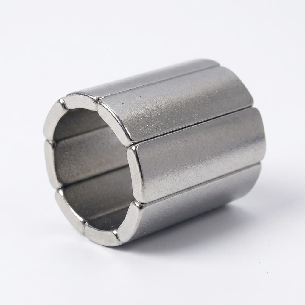
Laminated NdFeB Magnets for High-Speed PMSM Rotors: Eddy Current Loss Mitigation, Tolerance Stack-Up, and Sourcing Guardrails
Specify laminated NdFeB magnets for PMSM rotors: compare eddy current models, bond-line stack-up, insulation checks, and RFQ requirements. Use our checklist.
Laminated NdFeB magnets can reduce rotor magnet eddy current loss by dividing conductive blocks or arc segments into electrically isolated pieces. For high-speed permanent magnet synchronous motors (PMSM), the decision depends on the harmonic flux seen by the rotor, segment orientation, insulation integrity, and the cost of making a qualified assembly. Switching frequency alone cannot determine whether lamination is worthwhile.
Reviewed: October 27, 2026. Scope: Sintered custom NdFeB rotor magnets for global OEM engineering and procurement teams, with radial-flux PMSM examples. Axial-flux machines require their own field and segmentation model. This guide excludes bonded-magnet production and rotor release approval. Calculations below are reproducible screening examples, not measured supplier results, guaranteed savings, or rotor qualification data.
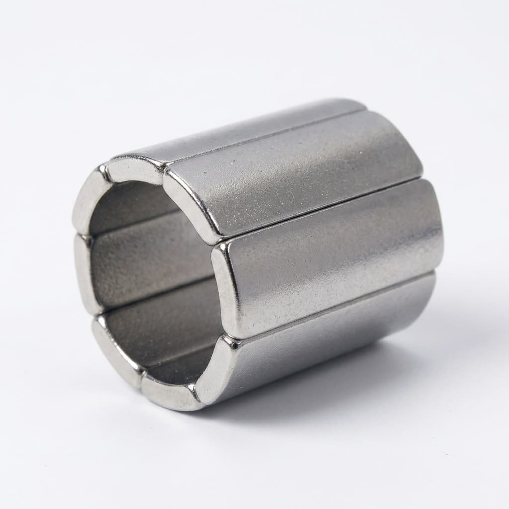
Rotor magnet heating can consume the demagnetization and adhesive temperature margins available to a design. Lamination adds insulating interfaces that interrupt selected current paths, but also introduces bond lines, extra handling, dimensional stack-up, and inspection costs. Arnold's L-Type product page confirms commercial NdFeB laminated constructions, including magnet layers from 0.5 mm and insulating layers below 20 µm for that product family. These are supplier-specific capabilities, not universal limits or our own production guarantees.
This guide helps motor designers and buyers decide what to simulate, what to put on the drawing, and what evidence to request before awarding a custom magnet order. For an initial feasibility discussion, send your rotor magnet envelope and operating conditions; the checklist below defines the remaining RFQ inputs.
1. The Electromagnetic Physics: Skin Depth and Loss Scaling
The relevant excitation is the time-varying magnetic field in the rotor reference frame. In an ideal synchronous operating condition, the fundamental field is stationary relative to the magnets. Slotting, winding space harmonics, PWM sidebands, and transients can still induce currents. Do not substitute stator electrical frequency or inverter carrier frequency for a rotor-frame harmonic spectrum without checking the field model.
For a uniform, linear conductor under sinusoidal excitation, classical skin depth is:
δ = √[ρ / (π × f × μ₀ × μᵣ)]
Here, ρ is electrical resistivity in Ω·m, f is the rotor-frame harmonic frequency in Hz, μ₀ = 4π × 10⁻⁷ H/m, and μᵣ is relative permeability. MIT's Skin Effect chapter explains this diffusion model and its thin- and thick-conductor limits. Applying it to a finite rotor magnet is a screening approximation.
For the worked calculations below, assume ρ = 1.5 × 10⁻⁶ Ω·m and μᵣ = 1.05. Replace these assumed material inputs with grade- and temperature-specific supplier data for design work.
The Two Operating Regimes: Resistance-Limited vs. Skin-Limited
- Resistance-limited approximation (d much smaller than δ): With sinusoidal, approximately uniform flux, an ideal thin-sheet model gives loss per unit volume proportional to
d² × f² × B² / ρ. Here, d is the current-path dimension reduced by the cut, and B is harmonic flux amplitude. Dividing a 10 mm path into five insulated 2 mm paths gives an idealized ratio(2/10)² = 0.04, or 96% lower loss for that modeled component. This assumes equal material volume and imposed flux, omits bond-line volume and three-dimensional end effects, and does not predict total rotor loss. - Skin-effect regime (d comparable to or larger than δ): Field penetration and induced-current reaction alter the loss distribution. The simple square-law estimate no longer suffices. Use a finite-geometry electromagnetic model with actual insulation, sleeve conductivity, and harmonic excitation; thinner segmentation does not guarantee a particular temperature or efficiency improvement.
Physical Comparison: Bulk Solid Magnet vs. Laminated Magnet Stack
Figure 1: Conceptual current paths, not measured loss or temperature data. Segment direction must interrupt the dominant current loops; the drawing is not to scale.
The following values are calculated screening results, rounded to two decimals using the stated inputs. Frequency alone supplies neither an optimum slice thickness nor a loss-reduction percentage.
| Rotor-frame harmonic frequency | Calculated skin depth δ | What this tells the engineer | RFQ / validation action |
|---|---|---|---|
| 500 Hz | 26.90 mm | Compare with the actual current-loop dimensions; a low frequency does not establish negligible loss. | Retain harmonic amplitude and solid-magnet loss baseline. |
| 1 kHz | 19.02 mm | A small slice can be below skin depth while a long magnet remains three-dimensional. | Identify the dimension and paths each cut interrupts. |
| 5 kHz | 8.51 mm | Slot-related or other harmonics require the machine's own spectrum. | Compare axial and circumferential segmentation in the model. |
| 10 kHz | 6.02 mm | Flux amplitude remains necessary to estimate loss. | Supply the operating point and harmonic amplitudes. |
| 20 kHz | 4.25 mm | Skin depth is above 2 mm under these assumptions. | Do not infer a mandatory submillimeter slice from carrier frequency. |
| 50 kHz | 2.69 mm | Some current-path dimensions may approach the skin-effect regime. | Check mesh convergence and insulation continuity. |
| 100 kHz | 1.90 mm | A 2 mm dimension is comparable to skin depth. | Use a suitable finite-geometry model and thermal validation. |
Selection boundary: Compare feasible segment counts against a solid baseline using the same operating points, imposed excitation, and thermal boundary conditions. Request the supplier's achievable slice thickness, kerf, bond-line capability, and yield assumptions. A sub-0.5 mm request needs specific manufacturing evidence; it is not a universal prohibition.
2. Lamination Architecture: Slicing Direction, Glue Lines, and Encapsulation
The assembly drawing must define the cut planes, electrical isolation, adhesive system, and protective coating. An adhesive joint and a rotor retention system have different functions.
Exploded View: Laminated NdFeB Segment Construction & Layer Specs
Figure 2: Conceptual bonded stack with dielectric interfaces and outer protection. Layer thicknesses are exaggerated for clarity; coating and adhesive specifications require qualification.
Slicing Orientation: Axial vs. Circumferential
For a simplified radial harmonic field, important current paths can extend axially and circumferentially. Real machines also have end effects and other flux components.
- Axial segmentation: Cut planes perpendicular to the rotor axis divide the magnet along its axial length and interrupt axial current paths.
- Circumferential segmentation: Cut planes divide the pole width into circumferential pieces, interrupting paths across that width. This is distinct from splitting the magnet through its radial thickness.
- Combined segmentation: Cuts in both directions add interfaces and assembly complexity. Compare the additional loss reduction with bonding, handling, and inspection effort rather than assuming maximum segmentation is best.
Choose orientation from the rotor-frame loss model and the mechanical drawing. Neither axial nor circumferential cuts are automatically superior for every arc magnet.
The Inter-Laminar Dielectric Layer
The bond line must maintain electrical isolation and mechanical integrity across the specified temperature, fluid exposure, vibration, and service life. Specify adhesive identity, surface preparation, cure, bond-line range, and acceptance tests together. Adhesive bulk resistivity alone cannot prove that a finished stack has no conductive bridges.
Use hot and aged joint data on representative magnet surfaces to qualify the process. ASTM D1002 describes comparative apparent lap-shear testing of metal-to-metal specimens; it does not supply a universal minimum bond strength or a rotor design-allowable stress. Define any adaptations to magnet coupons and qualify retention independently, including centrifugal loading, fatigue, and overspeed conditions.
Coating Architecture: Avoid Conductive Bridges
Metallic Ni-Cu-Ni coatings do not automatically short every laminated design, but metal contact, grinding debris, or a continuous conductive outer coating can bypass insulating seams. A dielectric coating on the outside also cannot repair an already shorted internal interface.
Agree a process route that preserves corrosion protection and seam isolation:
- Machine slices and qualify surface preparation for the selected adhesive and coating.
- Bond in a controlled fixture with defined cure and bond-line thickness.
- Finish functional faces only where needed, controlling swarf and seam damage.
- Verify adjacent-slice isolation at accessible test points, then apply the qualified outer protection and repeat the agreed accessible final checks. Include representative coupons or additional process controls where encapsulation hides the interfaces.
E-coat or Parylene can be candidates for external protection; chemical compatibility, adhesion, coverage, and temperature durability require evidence for the actual assembly.
3. Manufacturing Dilemmas: Kerf Loss, Stack-Up, and Conductive Bridges
1. Separate Slicing Yield from Finished Magnetic Fill Factor
Kerf is material removed during slicing; bond lines occupy space in the finished assembly. They belong in different calculations. The following is an illustrative one-dimensional material balance, excluding outer coating, end trimming, and finish-grind allowance:
- Ten finished slices at 1.000 mm contain 10.000 mm of magnetic material.
- Nine assumed 0.200 mm saw cuts require at least 11.800 mm of starting blank length. Slicing yield is
10.000 / 11.800 = 84.75%. - Nine assumed 0.025 mm bond lines produce a 10.225 mm finished stack. Magnetic fill factor is
10.000 / 10.225 = 97.80%. - If the finished slot envelope must instead remain 10.000 mm, the slices together can occupy only 9.775 mm, or 0.9775 mm per slice, before allowing for outer coating.
Thus, kerf increases raw-material consumption; it is not an extra void in a finished stack made from correctly sized slices. Nonmagnetic interfaces reduce active magnetic volume, but do not reduce the remaining magnet material's intrinsic remanence Br. Changes in air-gap flux or torque require the actual magnetic-circuit model. A higher grade is not an automatic compensation because coercivity and thermal margins must also be preserved.
2. Dimensional Tolerance Stack-Up
Specify the finished stack envelope and datums separately from individual slice dimensions. Our custom NdFeB magnet tolerance guide provides related DFM context; it is not a capability guarantee for a laminated assembly.
For an illustrative ten-slice stack with each slice at ±0.020 mm and each of nine bond lines at ±0.010 mm:
- Slice worst-case contribution:
10 × 0.020 = ±0.200 mm. - Bond-line worst-case contribution:
9 × 0.010 = ±0.090 mm. - Combined worst-case tolerance is ±0.290 mm, before coating, fixture, and thermal effects.
This is an arithmetic worst-case sum, not a statistical result. An RSS estimate would require justified assumptions about independent variation and process centering. If the assembly needs ±0.050 mm, agree how the supplier will achieve it through fixture control, slice selection, qualified finish grinding, or another demonstrated process. State whether acceptance dimensions include the final coating.
3. Conductive Bridges After Finishing
Grinding swarf, exposed conductive coatings, or damaged bond lines can electrically reconnect segments. Inspect seam edges and verify isolation after operations that could introduce a bridge. Do not prescribe a universal feed-rate reduction or an acid wash: cleaning chemistry and machining settings must be validated for the magnet, adhesive, and corrosion protection.
Define probe locations, test voltage, dwell time, temperature, humidity, minimum resistance, and sampling coverage. For example, 100 V DC and greater than 1 MΩ may be proposed for discussion, but are not a published universal acceptance rule in the sources below. Confirm that the method can detect the relevant bridge without damaging the dielectric, and repeat the agreed checks after aging.
4. Solid vs. Laminated NdFeB: Engineering & Procurement Trade-Offs
Use this decision matrix to compare quotations against the same finished-envelope and qualification requirements. It contains no assumed market price or performance guarantee.
| Evaluation metric | Bulk solid sintered NdFeB | Laminated / segmented NdFeB | Sourcing evidence to request |
|---|---|---|---|
| Magnet eddy current loss | Establish the machine-specific baseline. | Can interrupt selected current paths; improvement depends on geometry and spectrum. | Comparable loss maps at continuous, peak, and relevant transient conditions. |
| Magnetic fill factor | No internal adhesive interfaces. | Bond lines occupy part of the finished envelope. | Slice count, bond-line range, outer coating, and modeled air-gap flux. |
| Material utilization | Fewer segmentation cuts. | Additional cuts consume raw blank material. | Kerf allowance and material-yield assumptions, separately from finished fill factor. |
| Unit cost | Baseline quote for the same grade and volume. | Adds slicing, bonding, fixtures, and inspection. | Itemized prototype and series quotes; no universal cost multiplier. |
| Finished dimensional fit | Ground and coated part dimensions. | Cumulative slice and bond-line variation must be controlled. | Final coated-stack dimensions, datums, and inspection report. |
| Mechanical retention | Brittle magnet still requires a retention design. | Adds bonded interfaces and possible peel or fatigue failure modes. | Representative hot/aged joint tests plus independent rotor retention validation. |
| Thermal and fluid durability | Grade, load line, coating, and environment matter. | Adhesive and interfaces add constraints. | Demagnetization assessment and assembly-specific aging in the actual fluid. |
| Lead time and quality control | Baseline production and qualification schedule. | Extra process and electrical checks may extend delivery. | Supplier schedule, first-article plan, and isolation-test coverage. |
5. Engineering & Procurement Checklist for Laminated Magnet RFQs
Resolve these inputs before comparing suppliers. If the loss model is incomplete, request a feasibility review with the known inputs and identify the missing data explicitly.
- Operating envelope: Supply rotor speed range, duty, magnet temperature, cooling conditions, and rotor-frame harmonic amplitudes/frequencies or the model used to derive them.
- Geometry and orientation: Define slice count, cut planes relative to the rotor axis, magnetization direction, material grade, and the finished envelope.
- Bond-line control: Agree nominal thickness and variation with supplier capability data, including surface preparation and cure records.
- Isolation acceptance: Define resistance threshold, test voltage, dwell, probe locations, environmental conditions, and coverage at relevant manufacturing stages. Treat suggested values as proposals until qualified.
- Mechanical qualification: Define representative hot/aged joint tests and the rotor's retention, fatigue, and overspeed validation. Do not use a room-temperature lap-shear number as a rotor release criterion.
- Coating architecture: Prevent conductive paths across seams and verify corrosion protection after machining and bonding.
- Environmental durability: Specify actual fluid, temperature, exposure duration, and thermal-cycle profile from the service requirement, with post-aging isolation and mechanical acceptance criteria.
- Finished dimensions: Identify datums and tolerances for the bonded, coated stack; separate them from slice and glue-line tolerances.
- Commercial comparability: Align material yield, tooling, quantities, inspection records, delivery terms, and first-article versus series pricing.
6. Frequently Asked Questions (FAQ)
Q1: When should an engineering team switch from solid NdFeB to laminated magnets?
A: When a rotor-frame electromagnetic and thermal assessment shows magnet eddy current loss materially limits the design, and a manufacturable segmented option improves the result enough to justify its cost and qualification effort. Compare changes in excitation, cooling, geometry, and segmentation. A higher-coercivity GBD grade can improve demagnetization margin but does not remove eddy current heat. Neither a carrier-frequency threshold nor a fixed temperature margin is a universal switching rule.
Q2: Why can laminated NdFeB magnets cost more than solid magnets?
A: Slicing consumes material and adds handling; bonding needs controlled preparation, fixtures, and cure; finishing and isolation checks add work. Ask for these costs separately at the intended production volume. A claim that every laminated magnet costs three times as much is not a reliable budget basis.
Q3: How do we verify the insulation between slices?
A: Use an agreed adjacent-slice resistance method with accessible test points and controlled voltage, dwell, and environment. Include checks after potentially bridging operations and representative hot/aged qualification. State how interfaces hidden by encapsulation will be covered. No single resistance value proves low AC loss, bond durability, or rotor readiness.
Q4: Can laminated magnets use arc segment geometries for PMSM rotors?
A: Yes, but require supplier confirmation for the specific radii, slice thickness, magnetization, and coating. Select axial or circumferential cuts from the loss model and retention design, then agree finishing datums and inspection access. The simplest fixture is not necessarily the best electromagnetic solution.
Q5: What changes for magnets exposed to hot automatic transmission fluid (ATF)?
A: Qualify the adhesive, surface preparation, and protective coating together in the exact fluid and temperature profile. Specify dimensional change, isolation, and mechanical acceptance after immersion and thermal cycling. A generic resin name or coating choice cannot establish long-term compatibility, and an arbitrary immersion duration does not establish service life.
7. Next Steps for Custom Laminated Magnet Programs
Explore our custom NdFeB magnet product families for geometry and material context. Then contact our team for a laminated-magnet feasibility review with the CAD envelope, candidate segmentation, magnetization direction, temperature and fluid exposure, operating spectrum, and annual volume. Ask for a documented DFM response and qualification plan before fixing the production drawing or comparing series prices.
Sources & References
These sources support the principles and method boundaries identified below. The skin-depth, fill-factor, and tolerance examples are calculations using the explicitly stated assumptions; they are not laboratory or customer results.
- Arnold Magnetic Technologies — L-Type Laminated Magnets: Primary manufacturer source for commercial rare-earth laminated magnets and its stated layer capabilities. It does not validate another supplier's process or guarantee a loss-reduction percentage.
- MIT, Electromagnetic Fields and Energy, Chapter 10.7 — Skin Effect: Academic source for sinusoidal magnetic diffusion and skin depth. Its idealized conductor model is not a complete PMSM rotor-loss calculation.
- ASTM International — ASTM D1002-10(2019): Standard record for comparative apparent shear testing of adhesively bonded metal lap joints. It does not set laminated-magnet IR thresholds, qualification life, or rotor design-allowable stresses. Specify the applicable edition and any specimen adaptations in the test plan.
Author

Categories
More Posts
How to Define Magnetization and Coating in Your NdFeB RFQ
A buyer-side specification framework for magnetization and coating that reduces quote ambiguity and lowers sample failure risk.
Halbach Array NdFeB Magnets: Magnetic Field Concentration, Repulsive Fixturing, and Sourcing Guardrails
Specify Halbach array NdFeB magnets with field design limits, fixture load screening, thermal joint checks and an RFQ checklist. Request a custom DFM review.
Sample-to-Mass Production Quality Gates for NdFeB OEM Programs
A buyer-side gate framework with deliverables, owner roles, and release criteria to keep NdFeB OEM supply stable from sample to mass production.