
Halbach Array NdFeB Magnets: Magnetic Field Concentration, Repulsive Fixturing, and Sourcing Guardrails
Specify Halbach array NdFeB magnets with field design limits, fixture load screening, thermal joint checks and an RFQ checklist. Request a custom DFM review.
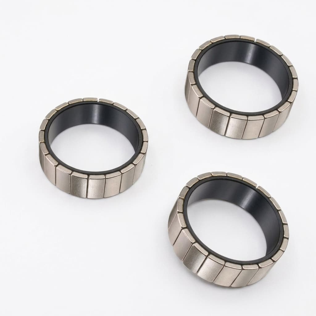
Halbach array NdFeB magnets use a rotating magnetization pattern to concentrate flux toward a working face or cylindrical bore while reducing the field elsewhere. Discrete 90-degree or 45-degree steps approximate the ideal continuous pattern. For custom NdFeB magnet procurement, the useful question is whether the required field, mass and space targets justify the extra segments, assembly tooling and inspection. A Halbach layout can reduce reliance on back iron, but its field gain and residual stray field must be evaluated for the actual geometry and air gap.
Reviewed: October 29, 2026. Scope: Custom sintered Neodymium-Iron-Boron (NdFeB) Halbach assemblies for global original equipment manufacturer (OEM) procurement, engineering, and quality teams. This guide covers linear planar arrays, arc-segment motor arrays, and hollow cylindrical Halbach cylinders. It excludes flexible bonded rubber strips and low-energy ferrite assemblies. The planar field equation does not apply directly to cylinders. Worked force and thermal calculations are screening examples with stated assumptions, not measured production results or guaranteed catalog ratings.
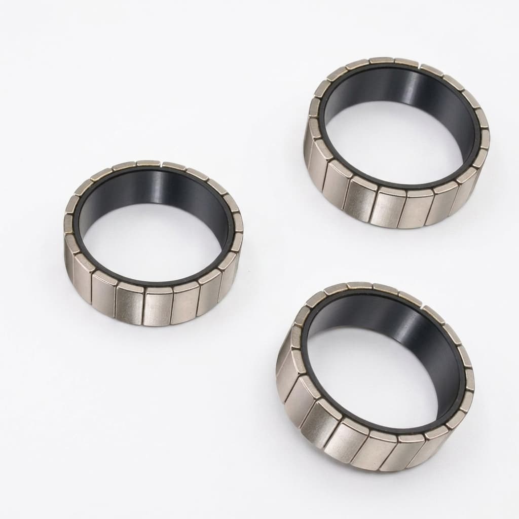
Product illustration: appearance alone does not establish the magnetization pattern or measured field. The vector schematic below explains the planar arrangement.
While simulation packages like ANSYS Maxwell and COMSOL readily generate idealized one-sided flux lines, manufacturing and procuring production-grade Halbach arrays introduces severe physical constraints:
- Attractive, repulsive and rotational assembly loads that vary throughout insertion and can cause edge chipping or injury without controlled fixturing.
- Magnetization vector angular errors that change weak-side leakage and the working-field waveform. Limits such as
±1.0°or±1.5°are possible RFQ targets, not universal requirements; derive them from the system field budget. - Anisotropic thermal expansion (CTE) across differently oriented blocks, which can load thin adhesive joints during thermal cycling. Obtain grade-specific coefficients and validate the complete coated joint.
This guide provides motor designers, roboticists, and procurement managers with the quantitative criteria needed to specify Halbach arrays, calculate fixturing overhead, audit magnetic alignment metrology, and submit qualified RFQs. For a direct engineering review of your custom envelope, contact our magnetics engineering group or explore our custom NdFeB magnet product catalog.
1. Electromagnetic Principles: One-Sided Flux and Discrete Segmentation Limits
The core mechanism of a Halbach array relies on the spatial superposition of magnetic flux from adjacent orthogonally oriented magnetic dipoles. In 1980, physicist Klaus Halbach published the analytical foundation for multipole arrangements using oriented rare-earth permanent magnet materials without soft-magnetic steel pole pieces. In 2001, Z. Q. Zhu and D. Howe expanded this analysis to permanent magnet brushless machines, establishing the modern framework for linear and rotary Halbach topologies.
The Ideal Continuous Halbach Field vs. Discrete Segment Scaling
In an ideal continuous planar sheet, the magnetization vector rotates through 360 degrees over one spatial wavelength λ, equal to two pole pitches (λ = 2τ_p). For an infinite planar array with relative recoil permeability approximated as one, no back iron and uniform remanence, the working-side field components are sinusoidal and the opposite-side field cancels. The fundamental peak component at lift-off distance z from the working face is:
B_g(z) = B_r × (1 - e^(-k × d)) × e^(-k × z)
Where:
k = 2π / λis the spatial wavenumber (k = π / τ_p).dis the total magnet thickness in the magnetization plane.zis the air-gap clearance between the magnet working face and the target plane.B_ris the material remanence at the stated temperature, taken from the supplier's grade data.
Conventional anisotropic sintered NdFeB blocks have a predominantly uniform easy-axis orientation set during manufacture. A later magnetizing pulse does not freely rotate that axis. Segmented Halbach layouts approximate continuous rotation using M separately oriented segments per magnetic pole pair (wavelength λ):
- 4 segments per pole pair (
M = 4): Magnetization rotates in 90-degree steps (for example, Right, Down, Left, Up). - 8 segments per pole pair (
M = 8): Magnetization rotates in 45-degree steps (for example, Right, Down-Right, Down, Down-Left, Left, Up-Left, Up, Up-Right).
The discrete segmentation introduces a reduction factor k_M to the fundamental working flux:
k_M = sin(π / M) / (π / M)
For standard 4-block segmentation (M = 4):
k_4 = sin(π / 4) / (π / 4) = (√2 / 2) / (0.7854) ≈ 0.9003
For 8-block segmentation (M = 8):
k_8 = sin(π / 8) / (π / 8) = (0.3827) / (0.3927) ≈ 0.9745
Under these ideal assumptions, moving from 4 to 8 segments increases the fundamental by approximately k_8 / k_4 - 1 = 8.2%. This is not an 8.2% guarantee for a finite motor assembly: gaps, curvature, end effects and magnetic material properties change the result. More segments also change the harmonic spectrum and double the segment count per wavelength. Use our custom magnet machining and tolerance guide to frame a supplier quote; grinding and bonding costs require an actual process breakdown.
The Weak-Side Cancellation Reality: Why Stray Field Is Never Truly Zero
Marketing materials sometimes advertise "zero flux" on the non-working side. A finite assembly has no universal cancellation percentage. Segmentation, end boundaries, block gaps, remanence variation and vector errors can all produce leakage. Finite thickness alone does not invalidate cancellation in the ideal continuous infinite-sheet model above.
Specify the maximum field at a defined weak-side distance and over a defined scan region, including the ends. For encoders or sensitive electronics, assess separation and a designed high-permeability flux return or shield. Austenitic stainless steel is generally unsuitable for static magnetic shielding merely because it is non-magnetic. Shield geometry, saturation and its effect on the working field need simulation and measurement; a generic foil thickness cannot guarantee a field limit.
2. Structural Vector Architecture and Interface Repulsion
The schematic illustrates 90-degree vector rotation with the stronger working side below the blocks. Jig markers identify constrained interfaces; they do not predict force direction or magnitude. Flux loops are illustrative, not a finite-element field map.
Planar Halbach Array: Magnetization Vectors and Constrained Interfaces
3. Assembly Mechanics: Repulsive Fixturing and Tooling Guardrails
Both conventional and Halbach arrays require controlled handling. In a Halbach assembly, differently oriented blocks can experience attraction, repulsion, transverse loads and torque as they move along the insertion path. A static final-position model is insufficient to size the assembly fixture. Blocks may rotate toward a different orientation if not restrained.
1. Screening the Fixture Load Scale
As a dimensional screening example only, assume a uniform normal field B = 1.0 T across an air-gap area A = 25 mm × 10 mm = 2.5 × 10⁻⁴ m². The magnetic pressure magnitude is:
p = B² / (2μ_0) ≈ 0.398 MPa, with μ_0 ≈ 4π × 10⁻⁷ H/m.
F = p × A ≈ 99.5 N.
This uniform-gap example is not a prediction of repulsion at an orthogonal Halbach joint, a worst-case load or a fixture rating. Real loads require the vector field, fringing, insertion position and torque, using a force model or measured force-displacement data. Require a documented fixture load envelope and design margin.
If an operator attempts manual assembly using basic hand clamps:
- Pinch Hazard: Attraction between blocks can overcome manual grip and cause an uncontrolled collision.
- Brittle Edge Fracturing: Impact can chip sintered NdFeB, damage protective coatings and introduce magnetic debris into the array.
- Adhesive Squeeze-Out and Starvation: Uncontrolled loads can displace uncured adhesive, leaving dry coating-to-coating contact and poorly bonded regions.
2. Sourcing Tooling Protocols: Non-Magnetic Mechanical Jigs
Request a supplier process that constrains unwanted translation and rotation during insertion and curing. The following is an RFQ discussion checklist, rather than a universal tooling design:
Assembly Tooling Guardrails for Halbach Sourcing:
├── Fixture Materials: Low-permeability stainless steel, aluminum, or brass
│   └── Verify actual magnetic response, stiffness, wear, and cure-temperature stability
├── Insertion Method: Guided motion with stops and controlled travel
│   └── Validate loads and torque throughout the selected insertion path
├── Clamping Architecture: Captive blocks and a controlled actuator or lead screw
│   └── Set clamp load from the adhesive process window and fixture load study
└── Cure Fixturing: Maintain alignment through the qualified cure and cool-down schedule- Guided Insertion: Axial or lateral sliding may provide a controllable route, but geometry and the load study determine the method. Do not permit unsupported freehand placement.
- Controlled Bond-Line Spacers: Agree on adhesive-compatible beads or shims and inspection of the resulting bond line. Bead diameter, loading and clamp pressure need joint qualification; adding filler is not automatically permitted by an adhesive datasheet.
4. Magnetization Vector Angle Tolerances & Metrology
A common specification gap is tight mechanical tolerances with no magnetization vector angular deviation limit (Δθ).
Vector errors can affect conventional and Halbach machines. For Halbach layouts, evaluate their effect on both the working-side waveform and weak-side leakage; mechanical squareness alone does not demonstrate magnetic alignment.
1. Vector Error Propagation and Harmonic Distortion
When individual segments exhibit angular errors:
- Weak-Side Leakage: Error magnitude and correlation between segments affect cancellation. There is no fixed leakage percentage for a given angular error across all geometries.
- Air-Gap Waveform Error: Field errors can create force or torque ripple; the affected harmonics depend on the error pattern. Cogging additionally requires interaction with a position-dependent magnetic reluctance, such as stator slots.
- Pole Asymmetry: Cylindrical assemblies may develop asymmetric fields and unbalanced forces. Check the actual rotor/stator system rather than assuming a bearing load from angle alone.
Illustrative RFQ angular-error budgets (not industry tolerance classes):
- Compare modeled field performance at errors of ±3°, ±1.5°, and ±1°.
- Choose a limit that satisfies the system field and ripple requirements.
- Define the mechanical datum, measured magnetic vector, and measurement uncertainty.
- Confirm supplier capability and the sampling or 100% screening plan before ordering.
2. Metrology Protocols: 3-Axis Helmholtz vs. Automated Gauss Mapping
Visual and coordinate-measuring machine (CMM) inspections cannot detect magnetic vector tilt. Sourcing contracts must stipulate two distinct magnetic quality gates:
-
Incoming Component Inspection (3-Axis Helmholtz Coil): An agreed, calibrated three-axis moment measurement can characterize individual blocks. With the block aligned to a defined mechanical datum, measure magnetic dipole moment components (
m_x,m_y,m_z) and calculate:θ_error = arccos[ m_principal / √(m_x² + m_y² + m_z²) ]Define the intended positive principal direction so that reversed polarity is rejected. This measures the net moment direction, not every local easy-axis deviation. Account for positioning error and instrument uncertainty. Sorting or pairing blocks may help, but the completed assembly still needs a field scan.
-
Final Subassembly Inspection (Automated Air-Gap Gauss Mapping): Once the Halbach array is bonded and cured, the supplier must pass a calibrated 3-axis Hall probe along the working face at the customer-specified lift-off distance
z(for example,z = 1.0 mm ± 0.02 mm). The resulting scan yields:-
Peak flux density and variation across the agreed scan region.
-
Zero-crossing positions and pole-pitch deviations relative to drawing datums.
-
Total Harmonic Distortion (THD) of the air-gap waveform:
THD = √(∑ B_n²) / B_1 × 100% (for n = 2 to ∞)In a measured scan, agree on the finite harmonic range, field component, sampling pitch, scan length and end exclusions. A THD target must follow the application's force or torque requirements; it is not a universal Halbach acceptance threshold.
-
5. Anisotropic Thermal Expansion (CTE) & Adhesive Joint Shear Fatigue
Thermal cycling can load Halbach adhesive joints even when the adhesive has a high temperature rating. Differently oriented blocks can expand differently along their shared interface. Debonding also depends on surface preparation, coating adhesion, cure, geometry and external loads; CTE mismatch alone does not diagnose a failed joint.
1. The Anisotropic Crystal Lattice Mechanism
Sintered NdFeB is anisotropic. Request parallel and transverse CTE data for the selected grade and temperature interval, rather than assuming one value for every supplier's material. For the illustrative calculation below only, assume constant α_∥ = +5.5 × 10⁻⁶ / °C and α_⊥ = -1.0 × 10⁻⁶ / °C. These are modeling inputs, not certified material limits from the cited papers.
2. Worked Engineering Calculation: Differential Joint Shear Strain
In a standard 90-degree planar Halbach array, consider the bonded interface between Block 1 (horizontal magnetization, M pointing right) and Block 2 (vertical magnetization, M pointing down):
Differential Thermal Expansion at Halbach 90° Joint:
┌────────────────────────┐  Bond Interface (Height L = 30 mm, Glue Line t = 25 µm)
│ Block 1: M →           │  ║  Block 2: M ↓
│ Easy axis HORIZONTAL   │  ║  Easy axis VERTICAL
│ Along interface: α_⊥   │  ║  Along interface: α_∥
│ α_⊥ ≈ -1.0 × 10⁻⁶ /°C  │  ║  α_∥ ≈ +5.5 × 10⁻⁶ /°C
└────────────────────────┘  ║  └────────────────────────┘
                              ▲
    Δα = α_∥ - α_⊥ ≈ 6.5 × 10⁻⁶ /°C  --> Differential displacement ΔL develops!
Assume the following hypothetical operating conditions:
- Joint interface height:
L = 30 mm. - Nominal adhesive bond-line thickness:
t_glue = 25 µm(0.025 mm). - Temperature excursion from room assembly (20 °C) to peak operating temperature (140 °C):
ΔT = 120 °C.
The differential thermal displacement ΔL between the two glued magnet faces along the joint is:
ΔL = L × (α_∥ - α_⊥) × ΔT
ΔL = 30 mm × (5.5 - (-1.0)) × 10⁻⁶ / °C × 120 °C
ΔL = 30 × 6.5 × 10⁻⁶ × 120 mm = 0.0234 mm = 23.4 µm
Divide the full-length free-expansion mismatch by bond-line thickness to obtain a dimensionless screening index γ_screen:
γ_screen = ΔL / t_glue = 23.4 µm / 25 µm ≈ 0.936 (93.6%)
This is not the actual uniform adhesive shear strain or a failure prediction. In a bonded joint, displacement and stress redistribute through the adherends, adhesive and carrier, with shear-lag and edge effects. The result flags a need for a joint model and thermal-cycle coupons. It cannot be compared directly with a datasheet tensile elongation value.
3. Engineering Mitigation and Adhesive Selection Guardrails
Increasing the assumed bond line to 50 µm halves γ_screen to 0.468, but does not establish a safe design. Adhesive stiffness versus temperature, coating adhesion, cure shrinkage and fatigue remain separate inputs.
Define these qualification requirements before series production:
- Adhesive and Coating Compatibility: Request strength retention over the operating temperature and environment range. ASTM D1002 is a comparative metal-to-metal lap-shear test method, not an adhesive certification or a design-allowable stress for the magnet joint. Test representative coated NdFeB joints and document any method adaptations.
- Qualified Bond-Line Thickness: Choose spacers, thickness and clamp load through joint analysis and coupons. Set thermal-cycle extremes, dwell times, cycle count, post-cycle bond acceptance and magnetic retest requirements for the application.
- External Mechanical Containment: For high-speed rotary arrays, specify engineered retention and overspeed validation rather than relying on adhesive strength alone. Sleeve material, interference and stresses require a rotor-specific design. For the sourcing trade-off, see our permanent magnet assembly fastening guide.
6. Magnetic Architecture Decision Matrix: Halbach vs. Conventional Arrays
Use this engineering decision matrix to evaluate whether a Halbach array is justified for your program, or if conventional alternating poles or monolithic multipole rings represent a lower-risk solution:
| Evaluation Metric | Conventional Alternating Array (N-S-N-S) | Discrete 4-Segment Halbach (90 deg Pitch) | Discrete 8-Segment Halbach (45 deg Pitch) | Monolithic Multi-Pole Sintered Ring | Sourcing Verification Evidence |
|---|---|---|---|---|---|
| Working Air-Gap Field | Establish a baseline at the required gap and envelope. | Ideal planar fundamental factor k_4 ≈ 0.9003. | Ideal planar factor k_8 ≈ 0.9745; compare finite geometry separately. | Orientation pattern and material capability determine the field. | Like-for-like simulation and calibrated field scan at the same lift-off and temperature. |
| Back-Iron / Yoke | Often used as a flux return; application dependent. | May reduce or remove the yoke if leakage and stiffness allow. | More segments do not guarantee zero leakage or eliminate structural support. | Radial multipole magnetization alone does not establish a Halbach pattern. | Working-side and weak-side field maps, including array ends. |
| Waveform / THD | Depends on pole shape, gaps and magnetic circuit. | Segmentation creates spatial harmonics. | Closer to continuous rotation, with a different harmonic spectrum. | Depends on attainable orientation and magnetizing fixture. | FFT of a scan with defined component, pitch, length and harmonic range. |
| Assembly Fixturing | Control attraction to the carrier and between blocks. | Restrain blocks along the full insertion path. | More pieces and orientations require a qualified assembly sequence. | No intersegment bonds, but installation and retention still require tooling. | Supplier process plan and fixture load/torque assessment. |
| Vector Tolerance | Derive from the application field budget. | Compare field sensitivity to proposed angular-error limits. | Evaluate whether added segments justify tighter sorting. | Confirm orientation feasibility before ordering magnetizing tools. | Calibrated vector inspection with datum and uncertainty defined. |
| Thermal Joint Risk | Carrier and coating mismatch can still load bonds. | Orthogonal orientations can create differential expansion. | Assess all rotated CTE tensors and carrier constraints. | No intersegment adhesive joints; carrier mismatch and ring stress remain. | Representative joint tests with agreed cycling and post-test acceptance. |
| Tooling & Unit Cost | Obtain a baseline at the same quantity and acceptance level. | Quote grinding, assembly, inspection and non-recurring tooling separately. | More segments can increase handling, bonding and inspection work. | Confirm die and magnetizing-fixture costs and achievable yield. | Itemized prototype and series quotes; no universal cost multiplier. |
| Selection Trigger | Suitable when a simpler magnetic circuit meets field and mass targets. | Candidate when one-sided field concentration has system value. | Candidate when improved field waveform justifies added complexity. | Candidate only when the required orientation is manufacturable. | System-level field, mass, thermal and cost comparison before tooling release. |
If the comparison leaves unresolved field or assembly requirements, request a custom Halbach DFM review with the same envelope and acceptance criteria for each quoted option.
7. Engineering & Sourcing Checklist for Halbach Array RFQs
Do not issue a Halbach array RFQ with only a 3D CAD step file. Ensure the following 9 engineering parameters are formally frozen on your production drawing and RFQ package:
- 1. Segmentation Architecture & Periodicity: Define total pole pairs (
p), spatial wavelength (λ), and segment count per pole pair (M = 4orM = 8). Clearly label magnetization vectors on every block drawing using standardized polarity arrows (Right, Down, Left, Up). - 2. Magnet Grade & Thermal Demagnetization Margin: Specify full material grade including thermal rating (for example, N45SH, N42UH, or N38EH) based on operating permeance coefficient (
P_c) and maximum working temperature. Consult our NdFeB demagnetization prevention guide to verify load-line stability. - 3. Magnetization Vector Angular Tolerance (
Δθ): Derive the limit from a field sensitivity study;±1.0°and±1.5°are example budgets, not standard application classes. Define a calibrated measurement, mechanical datum, uncertainty and lot-screening plan. - 4. Individual Block Tolerances vs. Stack-Up Limits: Specify block and complete-array tolerances separately. Values such as
±0.03 mmper block and±0.08 mmoverall are drawing examples only; check segment count, bond lines and process capability. Identify primary datums. - 5. Adhesive Specification & Bond-Line Control: Specify the qualified adhesive, surface preparation, cure schedule, service environment and bond-line range. Define spacer compatibility, thickness inspection and thermal-cycle acceptance; an electrical insulation class is not a joint qualification.
- 6. Surface Coating & Edge Chamfers: Define coating chemistry, thickness, edge treatment, corrosion exposure and bonding compatibility. Agree on allowable chips and repair/rejection criteria. Select chamfers or radii that protect edges without compromising the working gap.
- 7. Assembly Fixturing Material Protocol: Require supplier confirmation of non-magnetic assembly tooling (austenitic stainless steel SS316, aluminum alloy, or brass). Prohibit manual freehand magnet positioning.
- 8. Air-Gap Gauss Mapping Acceptance: Define the working-side and weak-side inspection planes, scan region, field component, temperature and calibration. Agree on peak field, amplitude variation, pole-pitch error and harmonic limits. Specify whether every assembly is scanned and retain traceable results.
- 9. Mechanical Containment & Handling Safeguards: Specify retention and validation for rotary or high-acceleration loads. Require a handling plan and transport packaging assessed for the actual shipment by the carrier or qualified dangerous-goods specialist; a steel-lined box alone does not establish air-freight compliance.
8. Frequently Asked Questions (FAQ)
Q1: When is a Halbach array worth the extra cost over conventional magnet poles?
A: Compare complete systems at the same field, working gap, thermal envelope and production quantity. A Halbach layout may justify extra tooling when reduced back iron, lower stray field or a better waveform has measurable value. Include the carrier, retention, inspection and assembly yield in the quote. There is no universal cost premium or mass-saving percentage.
Q2: Why did our prototype Halbach array delaminate during thermal chamber testing?
A: Inspect the failure surface first: coating separation, adhesive/coating debonding and cohesive adhesive failure imply different corrective actions. Review cleaning, cure, bond-line control, carrier mismatch and operating loads alongside anisotropic CTE. Use representative coupons and a joint model to qualify a change. A thicker bond line or a higher elongation value alone does not prove the repair.
Q3: Can Halbach cylinders be magnetized as a single monolithic ring instead of multiple segments?
A: Do not assume that a standard sintered multipole ring can reproduce a Halbach cylinder. A magnetizing pulse cannot freely rotate the easy axis already set in anisotropic material. A single-piece route requires an appropriate orientation process or a different material route, such as isotropic bonded material, with its own performance limits. Request an orientation drawing, material data and a measured field map before paying for tooling; otherwise evaluate segmented blocks.
Q4: How does a buyer verify that a supplier actually met the ±1.0° magnetization angle tolerance?
A: Specify a signed vector measurement relative to a mechanical datum, a calibrated fixture and an uncertainty small enough to resolve the tolerance. Agree on 100% component screening or a documented sampling plan, and retain lot-linked results. A process capability index is not a sampling plan. Also require the completed-array field scan: net component moment alone cannot establish the local working or weak-side field.
Q5: What is the optimal segment thickness ratio for a planar Halbach array?
A: There is no single optimum without a field target and mass/cost constraint. With four equal segments, w = λ / 4 follows from the segmentation definition. In the ideal planar model, the thickness factor 1 - e^(-2πd/λ) is about 0.715 at d = 0.2λ and 0.957 at d = 0.5λ. It approaches one gradually. Compare the incremental field against added material, then validate the finite geometry and demagnetization margin.
9. Next Steps for Custom Halbach Magnet Programs
Sourcing Halbach arrays requires bridging advanced electromagnetic design with rigorous precision manufacturing. Before finalizing your mechanical enclosure or awarding series tooling:
- Review Envelope and Grade Feasibility: Explore our custom NdFeB magnet product configurations to inspect achievable tolerances, edge chamfering, and coating systems.
- Request an Engineering DFM Review: Contact our technical engineering team with your CAD solid model, field targets, working and weak-side inspection planes, thermal profile and expected quantity. Ask for an itemized proposal covering fixturing, vector metrology and joint qualification before awarding tooling.
Sources & References
These sources support the magnetic architecture and joint-test discussion. The screening calculations and RFQ examples are illustrative engineering analysis, not measured supplier capability. DOI metadata confirms the paper identities; publisher full-text access may require a subscription. Obtain grade-specific material data and application-specific validation separately.
- Klaus Halbach — Design of Permanent Multipole Magnets with Oriented Rare Earth Cobalt Material: Nuclear Instruments and Methods, Vol. 169, No. 1, 1980, pp. 1-10. The foundational paper establishing one-sided flux concentration and multipole rotation theory without iron yokes.
- Z. Q. Zhu & D. Howe — Halbach Permanent Magnet Machines and Applications: A Review: IEE Proceedings - Electric Power Applications, Vol. 148, No. 4, 2001, pp. 299-308. Background on Halbach machine topologies and their applications; not a supplier price list or a universal acceptance specification.
- ASTM International — ASTM D1002-10(2019): Comparative testing of metal-to-metal single-lap adhesive joints. Its published scope cautions against treating coupon apparent shear strength as a design-allowable stress for a different joint. It does not prescribe a Halbach adhesive chemistry, minimum strength or thermal-cycle life.
Author

Categories
More Posts

NdFeB Shape Selection Guide for OEM RFQ
A buyer-side playbook to choose NdFeB shapes, define RFQ inputs, and compare suppliers with fewer clarification loops and faster sample closure.
Custom NdFeB Magnet Tolerances: How Over-Specifying Dimensions Drives Up Your Unit Cost
A comprehensive guide for engineers and procurement teams on how to specify NdFeB tolerances correctly to avoid unnecessary diamond grinding costs and yield loss.

Rare Earth Permanent Magnets Market Update (May 2026): Buyer Playbook for NdFeB Grades, Tolerances, Magnetization, and Coatings
May 2026 NdFeB magnet market update for US/EU/APAC buyers: grade, tolerance, magnetization, coating, pricing, lead-time shifts, and RFQ actions to apply now.