
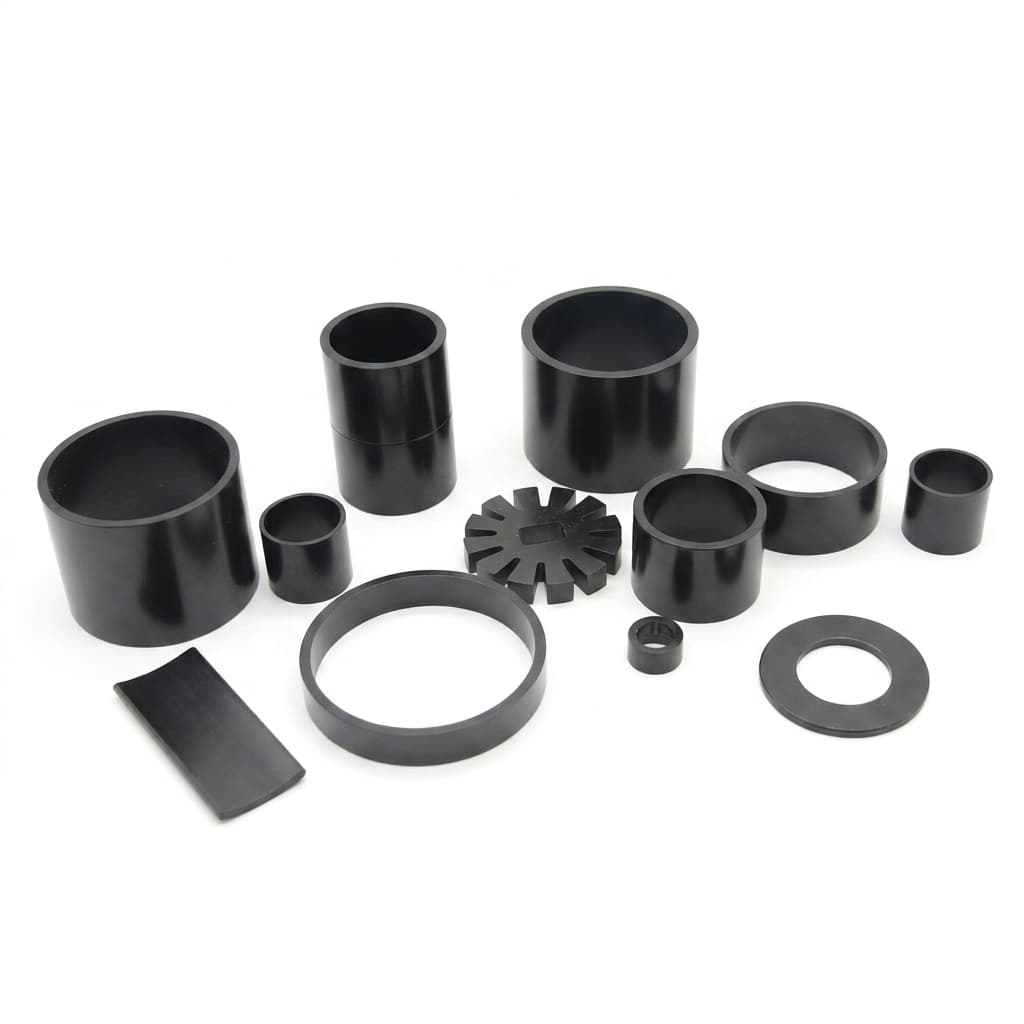
Wind Turbine Direct-Drive PM Generators (PMSG): Sintered NdFeB Wedge and Block Magnet Sourcing, C5-M Marine Corrosion, and 25-Year Thermal Stability
Source custom NdFeB magnets for wind turbine PMSGs. Compare marine coatings, thermal demagnetization, wedge tolerances, and OEM test evidence before an RFQ.
Wind turbine NdFeB magnets for permanent magnet synchronous generators (PMSGs) should be sourced against a rotor-specific magnetic, environmental, and assembly specification. A grade name such as N42SH, a salt-spray duration, or a quoted maximum temperature cannot establish offshore suitability or 25-year stability by itself. Buyers need hot demagnetization curves, representative coated-part qualification, and acceptance limits tied to the actual generator design.
Reviewed: November 9, 2026. Scope: Custom sintered NdFeB wedge and block magnets for utility-scale direct-drive and medium-speed wind turbine PMSGs, for a global English-speaking engineering and procurement audience. This is a sourcing and validation guide, not a certification report, measured supplier comparison, grid-code interpretation, or service-life guarantee. Examples are screening calculations or proposed RFQ requirements; production limits require agreement between the generator designer, supplier, and test laboratory.
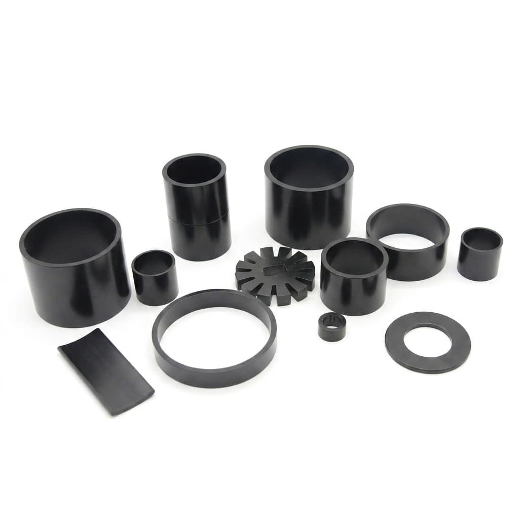
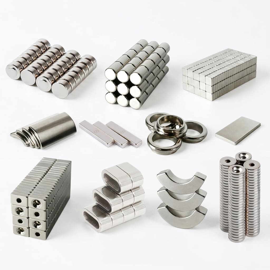
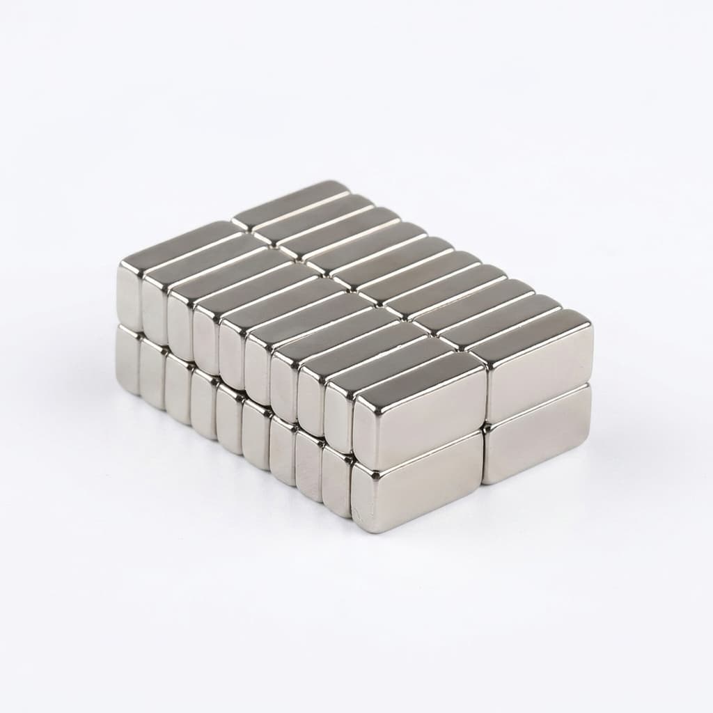
Catalogue illustration of custom magnet shapes. It does not show a qualified PMSG rotor pole or prove coating chemistry, grain boundary diffusion, or marine service life. The rotor schematic below illustrates the wedge assembly concept.
Offshore replacement logistics make evidence quality important: access, lifting equipment, weather windows, and lost generation can dominate the cost of a defective magnet. Those costs vary by project and should be priced in a sourcing risk model rather than assumed from a universal vessel day rate.
Three decisions should be resolved before comparing quotations:
- Marine protection: Which chloride, condensation, fluid, and handling exposures can reach the magnet, including when nacelle climate control is unavailable?
- Magnetic stability: Which local reverse fields and temperatures occur during normal operation, converter faults, short circuits, and recovery?
- Geometry and assembly: Which finished, coated dimensions control rotor fit, adhesive thickness, retention, and minimum running clearance?
Use the RFQ checklist in section 9 to assemble those inputs, then request a project-specific magnet feasibility review. The custom NdFeB product portfolio provides the shape and customization starting point.
1. Multi-Megawatt PMSG Architectures: Direct-Drive vs. Medium-Speed Geared Topologies
Direct-Drive Low-Speed PMSGs
Direct-drive generators couple to the turbine rotor without a speed-increasing gearbox. At a given mechanical power, reducing rotational speed increases shaft torque: T = P / ω. This usually drives a larger active diameter and a different pole arrangement than a faster generator. Magnet mass, pole count, air gap, and retention loads are design outputs, not quantities that can be inferred reliably from turbine megawatts alone.
For an illustrative calculation, 8 MW of mechanical shaft power at 10 rpm gives ω = 2π × 10 / 60 = 1.047 rad/s and torque of approximately 7.64 MN·m. This is shaft torque, not force on one magnet or an adhesive allowable. Individual pole loads still require the machine geometry, electromagnetic analysis, speed envelope, and retention model.
Specify whether the rotor is internal or external, whether magnets are surface-mounted or embedded, and whether poles are assembled from separate axial or circumferential segments. A drawing for a single block cannot establish the performance of the complete pole assembly.
Medium-Speed Hybrid PMSGs
A medium-speed architecture uses a gearbox before the generator. Higher generator speed changes rotor size, retention demands, and electrical frequency. Compare magnet eddy-current loss using the actual pole count, slot harmonics, converter waveform, and segment insulation; speed alone does not establish the loss or required grade.
Where the rotor yoke is laminated, include electrical-steel sheet insulation in its own material-control plan. IEC 60404-11:2021 concerns sheet and strip surface-insulation resistance. It is not a method for measuring permanent-magnet coercivity, and a compliant yoke does not prove adequate insulation between magnet segments.
2. Offshore Marine Atmospheric Exposure (C5-M / CX) and Intergranular Corrosion
C5-M is legacy marine-exposure terminology, not a universal NdFeB coating certificate. Current ISO 12944 specifications distinguish C5 and CX exposure categories; the applicable edition, environment, and protective-system scope must be stated. An offshore location does not automatically establish the corrosivity inside a sealed or climate-controlled generator.
The ISO 12944-6:2018 scope addresses protective paint systems for carbon-steel structures and explicitly says laboratory results do not provide exact durability predictions. Applying a similar test to an NdFeB part requires a defined adaptation and acceptance agreement; the steel-paint standard does not certify a magnet substrate or convert salt-spray hours into years offshore.
Sintered NdFeB contains a hard-magnetic Nd2Fe14B matrix and grain-boundary phases that can be particularly vulnerable to moisture and electrolytes. Corrosion can undermine cohesion, generate loose material, and lift or crack a protective barrier. Exact corrosion products, rates, swelling, and failure depth depend on alloy, processing, defects, and exposure. They should not be replaced by a single universal expansion percentage.
Assess likely entry paths: coating holidays, damaged chamfers, porous layers, contact with dissimilar metals, exposed ends, adhesive edges, and assembly damage. Specify inspection after handling and assembly as well as after coating. Inaccessible surfaces may require representative sectioned specimens or witness parts made with the same process.
Condensation, shutdown humidity, salt contamination, and fluid leaks should be considered together. Dehumidification may reduce exposure, but its availability and outage behavior belong in the system risk assessment. Coating, enclosure sealing, drainage, and climate control must be evaluated as an assembly.
3. Engineering Schematic: PMSG Rotor Pole Slot and Barrier Architecture
The conceptual cross-section identifies the interfaces that need separate requirements. It is not to scale, and the layer sequence is illustrative. Select coating chemistry, bond preparation, edge radius, gap, and retention from the actual design. On narrow screens, scroll the schematic horizontally to read the callouts.
Conceptual rotor interface: useful magnet flux points toward the air gap; an opposing local field can arise in some fault conditions. The depicted field is an explanation of a demagnetizing load case, not a prediction for every grid-voltage dip or converter architecture.
4. Multi-Layer Coating Systems: Test Protocols and Acceptance Criteria
Metallic layers, organic barriers, encapsulation, and compatible sealants are possible elements of a magnet protection system. No coating family is automatically adequate or inadequate for every offshore design. Ask the supplier for the qualified substrate, pretreatment, cure schedule, per-layer thickness distribution, edge coverage, repair policy, and compatibility with the rotor adhesive.
Ni-Cu-Ni is a multilayer stack; it should not be described as a single electroless deposit. Electroless nickel-phosphorus is a different process. Organic coatings can add electrical isolation, but isolation must be measured after compression, bonding, thermal cycling, and assembly damage. A face thickness reading cannot establish pinhole-free coverage or inter-segment resistance.
Zinc-flake systems and sealants may be candidates if their pretreatment and cure are compatible with the magnet and its delivered magnetic state. Avoid assuming that a non-electrolytic coating eliminates every hydrogen-related process risk. Cure temperatures and dwell times must also be included in magnetic qualification, particularly if parts are already magnetized.
The table below is a test-planning matrix, not a list of mandatory C5/CX magnet certification thresholds. The OEM and laboratory should select controlled method editions, specimens, exposure conditions, and damage limits before testing.
| Qualification question | Test approach | Inputs that must be written into the RFQ | Evidence needed for acceptance |
|---|---|---|---|
| Does salt exposure breach the barrier? | Neutral salt spray, such as ISO 9227 | Duration, solution, chamber conditions, scribed or intact specimens, edge treatment | Photographs and agreed blistering, corrosion, creep, and adhesion ratings; no service-life conversion |
| Can wet/dry exposure expose a different failure mode? | Defined cyclic-corrosion sequence | Exact sequence, durations, temperature, drying, and sample mounting | Full cycle log and damage mapping on representative coated magnets |
| Is the barrier stable in prolonged humidity? | Damp-heat screening or a separately defined pressure-cooker test | Temperature, RH, pressure basis, dwell, and recovery | Corrosion, mass change, adhesion, and magnetic retention where specified |
| Does adhesion survive manufacturing and aging? | Agreed tape, pull-off, or interface test | Applicable substrate, coating thickness, cut method, fixture, and rating scheme | Results before and after exposure; ASTM and ISO ratings reported in their own systems |
| Do expansion differences damage the assembly? | Defined thermal cycling | Low/high temperatures, ramp or transfer, dwell, cycles, and bonded condition | Edge cracks, delamination, bond integrity, fit, and flux checks |
| Are service fluids compatible? | Fluid immersion or splash testing | Actual oil, grease, coolant, concentration, temperature, and duration | Swelling, softening, adhesion loss, and dimensional change |
| Does a coating system preserve segment isolation? | Electrical resistance and dielectric testing | Fixture, electrode contact, voltage, compression, and humidity | Agreed electrical limits after assembly and aging, including edge contact |
Saturated pressure-cooker testing and unsaturated HAST are different exposures. Do not combine their names and select a temperature, pressure, and humidity arbitrarily. Pressure must identify absolute or gauge reference, and chamber conditions must be physically consistent. Similarly, two adhesion standards should not be treated as interchangeable rating certificates without an agreed method.
For quotation comparisons, send every bidder the same specimen drawing and test plan. A result on a flat steel panel, a thin magnet, or a different pretreatment cannot be silently transferred to a large coated wedge. Qualification reports should identify the exact part revision and manufacturing process.
5. Long-Term Thermal Aging and Irreversible Demagnetization under Faults
Separate reversible loss, irreversible loss, and corrosion
Reversible remanence loss changes while the magnet is hot and largely recovers after cooling if no irreversible process occurs. Irreversible demagnetization is the residual loss measured after returning to a common reference temperature. Corrosion-related material loss and changes in an adhesive fixture can also change measured flux, so the experiment must distinguish them.
For a screening arithmetic example, assume a supplier reports a reversible Br coefficient of −0.11%/°C over a stated interval. Heating from 20°C to 100°C gives an approximate reversible change of −0.11% × 80 = −8.8%. This linear estimate applies only within the coefficient's validated interval. It is neither a measurement on this supplier's magnets nor a prediction of irreversible loss after 25 years.
Evaluate local operating points and converter-dependent faults
In a simple no-load magnetic circuit, the load-line permeance coefficient can be written Pc = −B / (μ0 H) with consistent SI quantities. Actual operating points depend on geometry, leakage, saturation, temperature, and applied armature fields. Under load or a fault, use the local field solution rather than pretending every magnet shares one universal fault Pc.
The designer should compare local magnet polarization and field trajectories against temperature-dependent J-H curves, including recoil behavior and a stated knee-point definition. IEC 60404-5:2015 provides methods for permanent-magnet property measurement; it does not set a universal generator grade or approve service life.
A grid-voltage dip is not the same event as a generator-terminal short circuit. In a full-converter PMSG, the converter and protection system affect the generator-side response. Obtain separate current-versus-time load cases for normal control, grid ride-through, converter faults, terminal faults, and protection clearing. Applicable grid codes and connection agreements determine ride-through duties; there is no universal three-second requirement or fault-current multiplier that follows from the magnet grade.
Grain boundary diffusion and the evidence it requires
Grain boundary diffusion (GBD) can concentrate coercivity-enhancing elements near grain boundaries and reduce the need for bulk heavy rare-earth additions. Benefits depend on chemistry, geometry, diffusion treatment, and the finished magnet thickness. A GBD label does not establish a fixed Dy/Tb saving, a guaranteed remanence increase, or equivalent properties at the core and surface.
For thick or newly qualified parts, agree representative sampling from relevant locations, preparation methods that avoid changing magnetic properties, and hot magnetic measurements. Cross-sectional chemical mapping can support the process investigation, but ordinary SEM-EDS alone cannot resolve every nanoscale shell or prove local coercivity. Correlate chemical evidence with actual magnetic tests on appropriately prepared specimens.
Treat 25 years as a validation objective
A two-hour oven soak is a screening test, not proof of a 25-year loss budget. A defensible aging assessment defines the magnet geometry, load line, preconditioning, temperature-time mission profile, sample size, measurement uncertainty, environmental controls, and accepted residual flux loss after cooling.
If accelerated aging and extrapolation are proposed, justify the physical model and demonstrate that acceleration does not introduce a different failure mechanism. A flat early curve or an Arrhenius fit alone cannot guarantee decades of magnetic stability. Request the raw time-series data and model limitations, and keep the contractual lifetime target separate from the evidence available at production release.
6. Sintered NdFeB Grade Decision Matrix for Multi-Megawatt PMSGs
Use grade names to request comparable data, then select against the design envelope. The rows below identify candidate discussions, not measured product capabilities. Supplier grade definitions and property tolerances must be confirmed in the signed datasheet. Neither a temperature suffix nor a GBD process label specifies a 25-year aging allowance.
| Candidate grade or route | Why an engineer might shortlist it | Evidence needed before selection | Boundary or trade-off |
|---|---|---|---|
| N40SH | Starting candidate where moderate room-temperature flux is acceptable | Minimum Br, Hcj, hot curves, and fault-model margin | Lower Br may require geometry changes; suitability is not established by SH alone |
| N42SH | Compare flux and coercivity for an existing SH-class design | Same-temperature, same-method data against the current approved grade | Vendor grade names do not establish interchangeable hot behavior |
| N45SH | Investigate higher room-temperature energy product | Hot J-H curves, recoil behavior, dimensional envelope, and actual loss model | Additional room-temperature flux does not guarantee adequate hot fault margin |
| N38UH | Discuss coercivity-prioritized alternatives | Measured hot margin and the flux penalty in the actual circuit | Cost and material route are supplier-dependent; bulk alloying is not automatically obsolete |
| N42UH | Compare a higher-coercivity candidate with an SH shortlist | Geometry-specific thermal and reverse-field assessment | A UH suffix is not a converter-fault qualification |
| N45UH | Explore combined flux and coercivity requirements | Lot capabilities, core/surface evidence where needed, and hot acceptance data | Feasibility, yield, and commercial premium must be quoted for the actual dimensions |
| EH-class alternatives | Investigate a more demanding thermal or reverse-field envelope | Validated full-temperature curves and consequences for size, cooling, and cost | Higher coercivity can involve flux, availability, or cost trade-offs |
Before freezing a preferred row, send the thermal envelope and fault cases for an engineering RFQ review. Ask for exclusions and unverified requirements to be listed alongside the price rather than hidden in a generic grade certificate.
7. Geometric Tolerancing and Assembly Fixturing for Trapezoidal Wedge Poles
Sintered NdFeB is brittle, and geometry must be assessed after coating. Specify the mounting datum, magnetization axis, top and bottom widths, axial length, thickness, wedge angle, flatness, chamfers, and permitted edge damage. Distinguish substrate dimensions from final coated dimensions and identify the surfaces that receive adhesive or contact a retention rail.
Illustrative tolerance budget: if a coated block has two opposite faces each carrying 40 μm of coating, the finished dimension grows by approximately 2 × 40 μm = 0.08 mm along that axis. A drawing that allows only 0.05 mm of total clearance would already be incompatible with that nominal coating allowance before machining, layer variation, or assembly error. This calculation is geometric bookkeeping, not a recommended coating thickness or universal fit tolerance.
Do not apply a single ±0.05° wedge-angle rule to every rotor. Use a datum-based stack-up and assembly trial to determine permissible angle, width, and flatness. Separate block-to-slot fit from pole indexing around the rotor: they are related drawing controls, but individual wedge errors do not necessarily add as a free closed ring.
Magnetized delivery requires controlled fixtures, clean handling, pole identification, separation, and a validated installation sequence. Unmagnetized assembly reduces magnetic attraction during installation but retains brittle-part, adhesive, clamping, and lifting risks. It also requires a demonstrated post-assembly magnetization process with sufficient field throughout every pole. A fixed multiple of Hcj does not establish that capability.
8. Quality Assurance and Factory Acceptance Testing (FAT)
Agree a control plan that separates process qualification, first-article approval, routine lot release, and change requalification. Long environmental tests may qualify a process with periodic surveillance; they need not be invented as a universal test on every shipment. Define what happens when alloy, sintering, diffusion, machining, coating, adhesive, or factory location changes.
- Material and process traceability: Link finished part identifiers to alloy and sintering lots, diffusion records if applicable, machining revision, coating batch, and inspection results. Chemical composition is supporting evidence, not a replacement for magnetic properties.
- Dimensional and surface inspection: Report finished coated dimensions and sampling plans. Validate the coating-thickness measurement technique on this substrate and stack; a generic gauge setting may not isolate individual layers reliably.
- Magnetic acceptance: Define dipole moment, magnetic axis, reference temperature, fixture, calibration, and tolerances. Magnetic dipole moment in SI is expressed in A·m²; coil flux linkage or instrument readout is a different measured quantity. Moment consistency alone does not establish a universal Br tolerance or hot coercivity.
- Hot-loss screening: Document specimen shape, magnetic circuit, starting state, dwell, cooling conditions, and remeasurement at the same reference temperature. Set the accepted loss from the design budget and measurement uncertainty, not an unsupported industry-wide limit.
- Packaging and release: Protect coating edges, constrain movement, prevent moisture ingress, and label pole orientation. Obtain a transport assessment for the delivery's magnetic state, package, route, and mode. Air and sea requirements should not be collapsed into one unverified stray-field threshold.
Place nonconforming lots on hold under an agreed containment and disposition process. For critical failed measurements, preserve the original data and specimens so that a replacement report cannot erase the failure history.
9. Wind Turbine PMSG Sourcing and RFQ Checklist
Attach this checklist to the drawing and ask each supplier to respond with a value, supporting report, stated assumption, or explicit exception. Blank fields are unresolved requirements, not acceptance.
- Application: generator architecture, rotor layout, rated and maximum speed, pole/segment arrangement, installation location, and service environment.
- Magnetic envelope: minimum Br and Hcj at the reference temperature, complete hot curves, knee definition, recoil data, local operating-point analysis, and converter/protection fault cases.
- Thermal mission: continuous and transient magnet temperatures, cure and magnetization exposure, duty-cycle assumptions, and defined aging-loss objective with available evidence.
- Geometry: controlled CAD/drawing revision, datums, coated dimensions, wedge-angle tolerances, chamfers, bond surfaces, retention interfaces, and minimum clearances.
- Coating qualification: substrate and pretreatment, layer chemistry and thickness, edge coverage, exposure conditions, test method editions, damage ratings, and adhesive compatibility.
- Process route: bulk alloying or diffusion approach where relevant, evidence for finished thickness, traceability, approved manufacturing location, and change-control obligations.
- Acceptance: sampling plan, magnetic moment and axis limits, hot-loss procedure, gauge capability, first-article package, failed-lot containment, and requalification triggers.
- Commercial and delivery terms: delivery magnetic state, packaging validation, transport responsibility, project volume, release schedule, quotation validity, raw-material adjustment basis, and ownership of testing costs.
10. Frequently Asked Questions
Why not specify N52 to maximize magnetic flux?
N52 names a room-temperature energy-product class, not a hot fault operating envelope. Whether a particular product is suitable depends on its full grade, temperature-dependent coercivity, geometry, reverse fields, and cooling. Compare signed datasheets and simulations rather than assuming either universal suitability or inevitable failure from the number alone.
Does GBD automatically lower generator cost or LCOE?
No. It can reduce heavy rare-earth demand for a given magnetic target, but usable benefit depends on process yield, part thickness, price, qualification effort, and machine design. Calculate the project cost from equivalent hot performance and accepted reliability. A percentage reduction in Dy/Tb content does not translate directly into the same percentage LCOE saving.
If the nacelle is dehumidified, is marine protection still necessary?
Assess the residual exposure during normal running, outages, maintenance, and climate-control failure. The enclosure and protection strategy may reduce the magnet's actual exposure considerably. The required coating or encapsulation follows that assessment; neither dehumidification nor a C5-M label alone resolves the risk.
What causes wedge magnets to crack during rotor assembly?
Potential causes include interference after coating, mismatched bearing surfaces, edge damage, uncontrolled magnetic attraction, uneven clamping, and stresses from bonding or cure. Check contact patterns and finished dimensions before blaming the magnetic grade. Use representative assembly trials to validate fixtures and work instructions.
Can wind turbine magnets be reclaimed or recycled?
Recovery is possible through reuse or material-recycling routes, but access, adhesive removal, coating chemistry, contamination, and recycler capability affect feasibility. Agree dismantling records and material identification early. Any contractual recovery target or regulatory obligation must be assessed for the actual jurisdiction and project.
Can a supplier prove a 25-year irreversible flux-loss limit before shipment?
A short test cannot prove decades of service by itself. Request controlled aging data, the temperature and magnetic-circuit conditions, an explained extrapolation model, uncertainty, and any relevant field evidence. Separate an agreed lifetime target from a warranted commitment and from what the qualification data actually demonstrate.
11. Next Steps for Utility-Scale Wind Turbine Magnet Programs
Start with the failed-condition envelope, finished drawing, and qualification plan before requesting a production price. This lets procurement compare equivalent offers and exposes requirements that still need generator simulation, laboratory work, or assembly trials.
Review the custom NdFeB magnet product configurations, then contact the team with your drawing and RFQ checklist. Ask the response to identify feasible options, required samples, available reports, testing costs, and exceptions. Confirm demonstrated manufacturing and qualification capability before freezing a rotor design or placing a series order.
Sources and References
These primary catalogue records identify measurement or test scopes. They are not reports of tests on our magnets. Obtain the controlled editions needed for a project; the recommendations and illustrative arithmetic above are an engineering sourcing framework rather than measured supplier or field results.
- ISO — ISO 12944-6:2018, laboratory performance test methods: Defines the scope for protective paint systems on carbon-steel structures and cautions against treating laboratory results as exact durability predictions. Its scope is not an NdFeB certification.
- IEC — IEC 60404-5:2015, measurement of permanent-magnet properties: Covers magnetic-property measurements, demagnetization curves, and recoil lines. It does not establish 25-year generator life or a mandatory magnet grade.
- IEC — IEC 60404-11:2021, surface-insulation resistance of magnetic sheet and strip: Reference for a laminated electrical-steel material-control plan where applicable. The IEC catalogue identifies it as the successor to the older sheet-insulation edition; it is not a permanent-magnet demagnetization or grid ride-through standard.
Author

Categories
More Posts
Understanding and Preventing NdFeB Demagnetization: A Buyer's Guide
A comprehensive guide for procurement teams and engineers on how to prevent reversible, irreversible, and structural demagnetization in custom NdFeB magnets.
Halbach Array NdFeB Magnets: Magnetic Field Concentration, Repulsive Fixturing, and Sourcing Guardrails
Specify Halbach array NdFeB magnets with field design limits, fixture load screening, thermal joint checks and an RFQ checklist. Request a custom DFM review.
Evaluating NdFeB Coating Reliability: A Buyer's Guide to SST, PCT, and Edge Chamfering
Specify custom NdFeB magnet coatings with SST, PCT, and chamfer checks. Use this buyer guide to reduce corrosion risk before RFQ.