
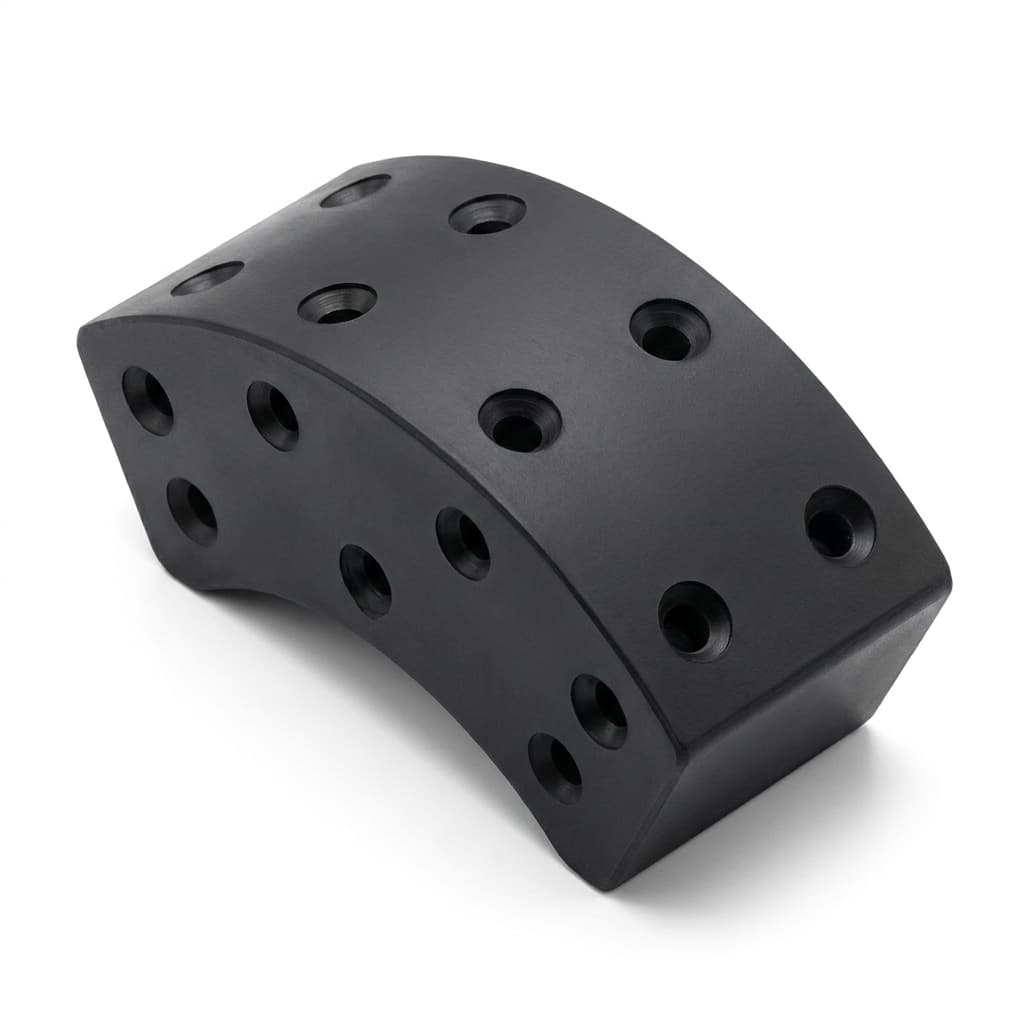
Robotic Joint Frameless Motor NdFeB Magnets: Breadloaf & Arc Segment Geometries, Back-EMF Harmonic Shaping, Peak-Stall Demagnetization Resistance, and OEM Sourcing Guardrails
Source custom NdFeB arc and breadloaf magnets for robotic frameless motors. Compare pole profiles, hot demagnetization evidence and OEM RFQ acceptance checks.
Robotic joint frameless motor NdFeB magnets should be sourced against the rotor geometry, magnetic orientation, hot demagnetization curves, and an agreed assembly validation plan. Concentric arc segments are a useful baseline; breadloaf profiles are candidates for shaping air-gap flux and back-EMF. Neither a shape name nor a catalogue grade establishes torque smoothness or survival during locked-rotor holding.
Reviewed: November 12, 2026. Scope: Custom sintered NdFeB arc and breadloaf segments for radial-flux internal-rotor and external-rotor frameless BLDC/PMSM kits, for global motor designers, robot OEMs, and procurement teams. Axial-flux designs and bonded isotropic rings are excluded. The drawing examples, calculation, and proposed inspection limits below are engineering screening aids, not measured production results, supplier guarantees, or rotor qualification certificates. No first-party motor test dataset is claimed.
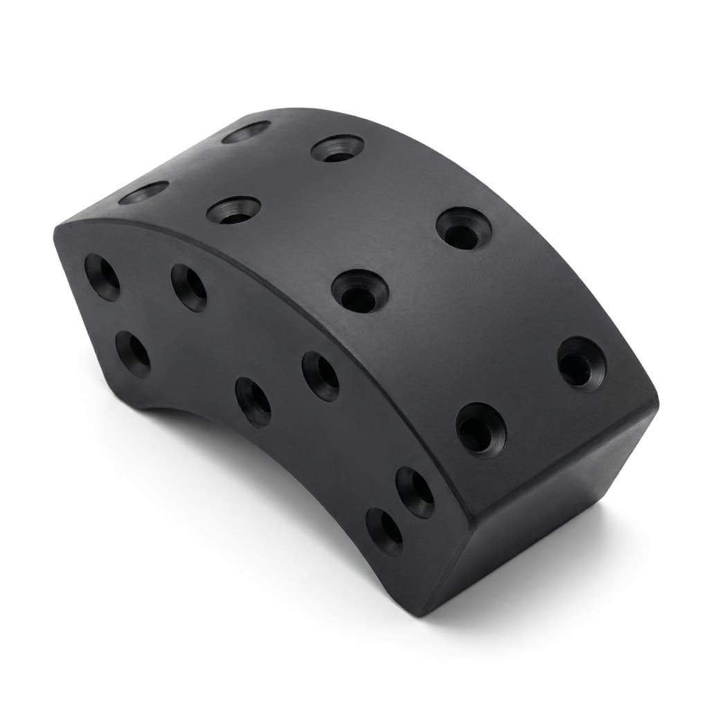
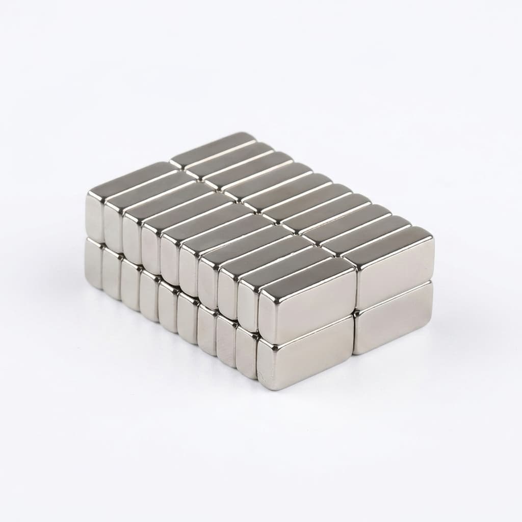
Catalogue illustration only. The depicted holes and surface finish are not a recommended rotor design or evidence of a qualified part. Use the conceptual SVG below for the geometry comparison.
A joint housing places the motor near bearings, gearing, electronics, and cable passages. Cooling and holding duty vary by design, so winding temperature cannot substitute for measured or modeled magnet temperature. High reduction gearing multiplies motor torque disturbances at the output, while control bandwidth, compliance, friction, and structural resonances determine how those disturbances affect positioning.
Before requesting quotations, decide three things:
- Pole profile: Compare concentric and breadloaf candidates using the same slot/pole combination, winding, current convention, and rotor envelope.
- Hot reverse-field case: Define magnet temperature, current magnitude and angle, duration, and fault cases before selecting a coercivity class.
- Assembly stack: Allocate the mechanical air gap across hub, bond line, magnet profile, coating, runout, retention sleeve, and thermal growth.
Use the RFQ and sourcing checklist, then submit drawings for a feasibility review. The custom NdFeB manufacturing portfolio provides the product context for that discussion.
1. Frameless Torque Motor Architectures in Robotic Joint Actuators
A frameless kit supplies rotor and stator components for integration into the customer's housing. The OEM therefore owns the bearing arrangement, concentricity, heat path, cable clearance, retention strategy, and assembly validation. A magnet supplier can assess manufacturability without approving the complete motor or robot joint.
Conceptual internal-rotor radial stack, outside to inside:
Stator bore
Mechanical clearance (including any retention sleeve allowance)
Magnet outer profile and coating
Sintered NdFeB segment
Structural adhesive bond line
Rotor back-iron / hollow hub
For an external rotor, the stator-facing surface and retention loads differ. Identify which member rotates and which radius is the bonding surface on the drawing; an internal-rotor sketch cannot simply be reused with unchanged dimensions.
Direct-Drive vs. Geared Joint Kinematics
With reduction ratio i = motor speed / output speed, ideal torque multiplication is i and motor inertia reflected to the output is J_motor × i². Gear efficiency and dynamics alter the actual response. Define torque ripple at a stated speed, current, and load; a common peak-to-peak convention is 100 × (T_max − T_min) / T_avg. This percentage is unsuitable when average torque is zero.
Cogging torque is the unenergized interaction of permanent magnets and stator slotting. Loaded electromagnetic torque ripple also depends on winding harmonics, drive current, saturation, and control. Require separate cogging and loaded-ripple measurements rather than using either one as a proxy for the other.
Space Envelope and Hollow-Shaft Integration
A thin back-iron sleeve may constrain flux capacity as well as mechanical stiffness. Use the actual steel B-H curve to check saturation; there is no universal flux-density threshold for every hub alloy. Assess leakage near magnetic encoders in the installed layout. Cable-bore requirements, rotor balance, and sleeve retention can change the useful magnet envelope before a grade change becomes necessary.
2. Breadloaf vs. Concentric Arc Profiles: Air-Gap Permeance Modulation and Harmonic Shaping
A concentric arc has inner and outer surfaces sharing a center, producing nominally uniform radial thickness. A breadloaf profile uses a curved outer face over a flat or curved mounting face to obtain a thicker center and thinner edges. Define both surface centers, offsets, and angular extent: the word “breadloaf” does not specify a unique radius relationship or interchangeable geometry.
Concentric Arc Profiles
Uniform-thickness segments are a useful reference for tooling, magnetic volume, and assembly. Their air-gap waveform depends on pole coverage, magnetization direction, stator slots, winding distribution, and saturation. They do not inherently produce a specified back-EMF THD. In a balanced three-phase system, triplen components cancel in line-to-line voltage; the remaining harmonic content still requires measurement or simulation.
Breadloaf and Eccentric Arc Shaping
Tapering the magnet changes both its source strength and the mechanical gap to a fixed stator bore. For a simple one-dimensional, equal-area circuit with negligible leakage and unsaturated iron, use:
B_g ≈ B_r × t_m / (t_m + μ_rec × g)Here B_r is remanence at the evaluation temperature, t_m is local magnet thickness, μ_rec is relative recoil permeability, and g is local nonmagnetic gap. A sleeve or coating requires its own thickness/permeability contribution. The equivalent reluctance length is g + t_m / μ_rec, but the magnet also provides the magnetic source. Changing thickness alone cannot be interpreted as changing an air gap with a fixed source.
At a tapered edge, t_m decreases and g generally increases. This can shape the spatial field, but it does not establish a sinusoidal waveform or protect the edge from demagnetization. Leakage, fringing, magnetization orientation, and slotting make finite-element analysis necessary for final decisions.
Harmonic Trade-Off: Fundamental Flux vs. THD
Compare candidates using fundamental back-EMF, the chosen THD bandwidth, fifth/seventh harmonics, cogging peak-to-peak torque, and loaded torque ripple. State whether back-EMF is phase or line-to-line and record test speed. At equal speed and voltage convention, the ratio of fundamental back-EMF provides a useful comparison of flux linkage. Compare torque constants using consistent phase-current and RMS/peak conventions.
There is no supported universal percentage for a breadloaf profile's THD reduction, cogging improvement, or torque penalty. Set project targets, evaluate both profiles under matched conditions, and retain the simpler concentric profile if the shaped candidate does not justify its tooling and inspection cost.
3. Engineering Schematic: Rotor Pole Shaping and Armature Demagnetizing Vectors
The illustration compares local developed cross-sections rather than a dimensioned circular rotor. It shows an example center gap of 0.50 mm and edge gap of 1.1 mm. Red arrows indicate possible local opposing fields for the illustrated pole polarities; actual field direction and magnitude depend on rotor position and stator current. The drawing is not an FEA result or a guaranteed reduction in harmonics.
Conceptual drawing, not to scale. Magnet colors identify pole polarity only; both profiles require independent hot reverse-field and retention checks.
4. Thermal Demagnetization at Locked-Rotor Stall: Operating Point and Knee-Point Trajectory
At zero speed, back-EMF is zero while holding current still produces copper loss. A continuous holding requirement needs a dedicated thermal operating point; a general continuous-duty label does not establish allowable stall torque. Record coolant or housing conditions, winding and magnet temperatures, holding duration, and the drive's current limit.
The Electromagnetics of Locked-Rotor Stall
In field-oriented control, a surface-PM motor often uses q-axis current for torque with a near-zero d-axis command. Stall does not inherently require negative d-axis current. Field weakening, faults, current-regulator transients, and position errors can create additional adverse cases. Even with zero commanded d-axis current, local armature fields can oppose parts of a magnet.
A multiple of rated current is therefore insufficient to state a demagnetization margin. Supply the actual phase-current waveform, peak/RMS convention, current angle, pulse duration, initial magnet temperature, and relevant rotor positions. Evaluate local elements of the magnet rather than averaging the entire pole.
A Reproducible Open-Circuit Screening Example
In an ideal equal-area circuit without leakage or iron reluctance, the positive permeance coefficient is P_c = B / (μ₀ × |H|) ≈ t_m / g. The absolute value matters because H is negative in the second quadrant. For an illustrative t_m = 3.0 mm, g = 0.50 mm, B_r = 1.30 T, and μ_rec = 1.05:
P_c ≈ 3.0 / 0.50 = 6.0
B_g ≈ 1.30 × 3.0 / (3.0 + 1.05 × 0.50) = 1.106 T
H_m ≈ −B_g × g / (μ₀ × t_m) = −147 kA/m
μ₀ = 4π × 10⁻⁷ H/m
These are selected example inputs, not a grade datasheet or a loaded motor prediction. Added armature MMF moves the operating point along the material response; it does not turn a fixed geometry into a universally lower “effective P_c.” Use temperature-specific B-H/J-H curves and local electromagnetic analysis to assess proximity to the knee, then check irreversible loss after the defined current/thermal cycle.
Grain Boundary Diffusion for High-Coercivity Grades
Grain boundary diffusion (GBD) is a processing option to raise coercivity while managing heavy rare-earth use and remanence trade-offs. Its result depends on material, dimensions, diffusion access, and process control. Request process-specific curves for the delivered thickness rather than assuming that every UH/EH grade uses GBD or achieves the same hot properties.
IEC 60404-5:2015 establishes measurement methods for permanent-magnet properties and demagnetization/recoil curves. It does not supply a universal robot stall limit. If specifying a squareness or knee-field ratio, define the knee criterion, temperature, measurement method, and acceptance value with the supplier; H_k is not meaningful without its definition.
5. Geometric Tolerancing and Curvature Stack-Up for High-Pole-Count Rotors
Build the air-gap budget from the finished assembly, including coating and adhesive. For an illustrative internal rotor with stator bore 80.00 mm, hub OD 72.80 mm, radial bond line 0.10 mm, and finished magnet center thickness 3.00 mm:
Rotor magnet OD = 72.80 + 2 × (0.10 + 3.00) = 79.00 mm
Nominal radial center gap = (80.00 − 79.00) / 2 = 0.50 mm
This nominal calculation excludes runout, sleeve thickness, bearing motion, thermal growth, and tolerances. Subtract their worst-case radial contributions before approving clearance. A statistical tolerance stack needs justified distributions and process capability; it cannot replace a worst-case assembly check without agreement.
Critical Geometric Callouts on Arc/Breadloaf Drawings
- Mounting face: Define inner radius or flat datum, hub fit, and the intended adhesive gap. Avoid specifying a radius tolerance without locating its center.
- Outer profile: Dimension the profile relative to assembly datums. An illustrative ±0.02 mm profile target is a quotation input to confirm, not a universal grinding capability.
- Finished thickness: State whether coating is included. A thickness error changes both the gap and magnet volume; its magnetic effect must be calculated for the actual circuit.
- Chord and pole arc: For a 20-pole rotor, pole pitch is 18 mechanical degrees. A selected 16-degree magnet arc leaves 2 degrees nominal inter-pole space; assess the chosen reference radius and cumulative placement errors.
- Axial straightness and runout: Allocate these against usable clearance and bond-line variation. Distinguish individual segment bow from assembled rotor runout.
- Chamfers and defects: Define edge breaks, allowed chip size and location, coating coverage, and critical bonding surfaces. An undefined “zero defects” requirement is difficult to inspect consistently.
Specify critical dimensions individually. A general tolerance class cannot establish a specific chord allowance, magnetic performance, or a guaranteed fit for a complete magnet set.
6. Sintered NdFeB Grade Decision Matrix for Robotic Actuators
Use grade labels to shortlist candidates, then compare supplier-specific room-temperature properties and hot curves. Arnold's NdFeB materials reference describes the remanence/coercivity trade-off and variation with alignment, size, and shape. Its catalogue data are context, not approval of another supplier's magnets.
The seven-row matrix specifies what to obtain before release. It deliberately assigns no hot coercivity minimum, cost index, or safe current multiplier from the label alone.
| Candidate | Question for selection | Evidence required from supplier | Release limitation |
|---|---|---|---|
| N48SH | Is the higher-energy option useful in this envelope? | Signed B_r and coercivity specification plus hot curves | Check local edge demagnetization at the declared current and temperature |
| N45SH, GBD candidate | Does diffusion improve the required hot margin? | Processing declaration and curves for delivered segment thickness | GBD is a process option, not proof of stall survival |
| N42SH | Can a lower-energy baseline satisfy torque and thermal targets? | Actual lot minima, temperature behavior, and magnetic orientation | Compare geometry and cooling under the same load cases |
| N45UH, GBD candidate | Is additional coercivity worth the quoted process cost? | Hot knee behavior and post-cycle loss data for agreed conditions | UH does not imply zero loss during a peak-current event |
| N42UH, GBD candidate | Does the balance of flux and coercivity fit the joint? | Same test method and temperatures as competing candidates | Evaluate fundamental flux and demagnetization together |
| N38UH | Can reduced magnetic output be accommodated? | Curves and motor-level torque/thermal assessment | More stator current may erase a material-cost benefit |
| N38EH, GBD candidate | Is the hotter or stronger reverse-field case decisive? | Temperature-specific curves and assembly compatibility evidence | Adhesive, coating, bearings, and electronics retain separate limits |
Compare quotations at the same drawing revision, quantity, yield assumptions, inspection coverage, tooling ownership, and delivery terms. Request the diffusion option and its incremental lead time as separate line items; no reliable universal surcharge or five-day process allowance follows from the grade name.
If the table leaves a required datum unresolved, request a documented material and process feasibility review before accepting an equivalent-grade substitution.
7. Structural Bonding, Thermal Cycling, and Rotor Assembly Guardrails
The rotor needs a retention design for its speed, acceleration, shock, temperature, and service life. Bonding, a retaining sleeve, and mechanical features share load differently in internal and external rotors. A nonmagnetic sleeve also occupies radial space and can affect losses. Agree which party owns retention analysis and validation.
Adhesive Selection and Bond-Line Thickness Control
Choose an adhesive using the actual coating, hub surface, cure process, operating temperature, and environment. A 0.10 mm bond line can be an initial drawing example, but the permissible range comes from the adhesive system and assembly qualification. Too little or too much adhesive may cause starvation, incomplete cure, creep, or placement problems; universal gap thresholds are inappropriate.
ASTM D1002 is a metal single-lap apparent-shear test method. Coupon strength is not directly an allowable design stress for a curved coated-magnet assembly, and the standard does not prescribe a universal minimum MPa value for robot rotors. Use representative substrates, coating condition, cure, aging, and temperature, then validate the actual joint. Check peel and fatigue as well as apparent shear.
Adhesive glass-transition temperature is useful context, but temperature relative to T_g alone cannot approve a bond. Obtain retained strength and creep information for the actual duty and include environmental exposure in the validation plan.
Surface Preparation and Protective Coatings
Ni-Cu-Ni normally describes a plated multilayer system; it should not be called an electroless Ni-Cu-Ni stack without a process-specific basis. Epoxy is another coating option. Thickness, porosity, adhesion, corrosion behavior, and dimensional allowance all require an agreed specification. Neither coating is universally best for every robotic joint.
Use the adhesive supplier's preparation instructions and confirm compatibility with the delivered coating. Cleaning, abrasion, primer, or plasma treatment must not damage corrosion protection. Establish a controlled process and verify the bond after aging rather than promising that plasma treatment prevents delamination.
Thermal Expansion Mismatch
Sintered NdFeB expansion is anisotropic and depends on orientation and material. Request relevant coefficients for the magnet and hub, then evaluate differential movement across the specified thermal cycle. A toughened adhesive may help accommodate strain, but its fatigue and creep performance still needs evidence. Record coating-to-substrate failure separately from adhesive failure when examining test specimens.
8. Quality Assurance and Factory Acceptance Testing
Magnet acceptance should cover drawing conformity, magnetic consistency, coating integrity, and traceability. Define inspection fixtures and uncertainty before setting tight limits; otherwise two laboratories can disagree while both follow their own undocumented setup.
1. Magnetic Consistency: Name the Measured Quantity
An integrating fluxmeter with a calibrated Helmholtz coil can be used to infer magnetic dipole moment through the appropriate fixture factor. Raw linked flux and magnetic moment are different quantities: report the instrument output, calibration factor, units, sample orientation, and reference temperature. Magnetic moment is expressed in A·m²; a flux reading in webers cannot simply be labeled a complete measure of magnet strength.
An illustrative ±1.5% sorting window is a proposed RFQ target, not a guaranteed manufacturing capability. Define it relative to an approved nominal reference, not solely to the current lot mean, so an entire weak lot cannot pass by matching itself. Agree sampling or 100% coverage based on process capability and risk. A total-moment check does not replace profile or orientation measurement.
2. Hall Mapping and Rotor Back-EMF
Specify probe axis, standoff, fixture datums, temperature, and scan path for Hall mapping. A small change in standoff can change a surface-field reading, so handheld peak Gauss alone is poor evidence for interchangeability. Compare maps under identical conditions; an isolated magnet scan is not the same as a complete rotor's air-gap field or back-EMF spectrum.
Measure assembled back-EMF at a stated speed and voltage convention. Test unenergized cogging separately from loaded torque ripple. Keep the agreed harmonic bandwidth and sampling method with the result so a supplier cannot report a favorable THD number using a different definition.
3. Thermal and Reverse-Field Qualification
For a proposed test, record sample dimensions and lot, initial moment at a reference temperature, hot exposure temperature/time, applied reverse field or actual current waveform, and the return-to-reference measurement. Calculate irreversible loss as 100 × (initial − final) / initial after allowing the sample to cool consistently.
A thermal-only open-circuit bake screens one condition; it cannot establish loaded stall resistance. Sample shape and its environment set the load line, so an oven setting does not define P_c. Agree sample size, acceptance limit, confidence expectations, and failure investigation with the OEM. Representative coupons need demonstrated relevance to the production segment, especially for thickness-dependent diffusion.
9. Robotic Joint Frameless Motor Magnet RFQ and Sourcing Checklist
Attach the following to the controlled drawing package. Mark unresolved fields as open engineering actions rather than allowing a supplier to infer requirements.
- Topology and envelope: Internal or external rotor, slot/pole count, hub dimensions, nominal/minimum gap, sleeve allowance, and rotation/speed limits.
- Geometry: STEP model revision, datums, mounting radius, outer profile centers/offsets, chord, axial length, finished thickness, and coating allowance.
- Assembly controls: Bond-line range, placement pitch, runout, balance, edge breaks, and measurable chip/defect acceptance.
- Material specification: Candidate grade, signed B_r/H_cB/H_cJ requirements, hot B-H/J-H curves, and agreed knee definition.
- Process and orientation: GBD or alternative process declaration, relevant diffusion thickness, magnetization axis, and acceptance method for orientation error.
- Duty and adverse cases: Magnet temperature, holding duration, current magnitude/angle and peak/RMS convention, field-weakening and fault cases.
- Surface protection: Coating type, thickness, corrosion and adhesion test conditions, approved preparation and adhesive cure process.
- Inspection evidence: Dimensional report, calibrated magnetic quantity/units, fixed reference limits, Hall mapping setup, and lot traceability.
- Qualification plan: Thermal-only and loaded reverse-field tests identified separately, irreversible-loss limit, sample count, and responsibility for assembled motor testing.
- Commercial controls: Prototype/series quantities, tooling charges and ownership, change notification, equivalent-grade approval, lead-time basis, delivery terms, and packaging.
- Delivery state: Magnetized or unmagnetized, pole marking, spacer protection, handling precautions, and approved assembly sequence.
10. Frequently Asked Questions
Why not use full ring magnets instead of segmented arc tiles?
A ring may reduce segment placement work but still needs retention to the hub. Radially oriented sintered rings, bonded multipole rings, and assemblies made from segments have different tooling and magnetic properties. Diameter, wall thickness, orientation, achievable yield, and tooling availability constrain each option. Segments can simplify profile changes and sourcing, but they also have size limits and require controlled assembly; neither approach is universally superior.
Can stator slot skewing replace breadloaf magnet shaping?
Skew is another harmonic-control variable. It can reduce selected cogging and back-EMF harmonics, while changing fundamental output and winding or lamination manufacturing requirements. Its effect depends on the chosen skew and slot/pole combination. Compare straight/skewed stators and concentric/shaped magnets in the same model; do not assume that one slot pitch eliminates every disturbance or that axial force is unavoidable.
What failure modes should a robotic joint OEM investigate?
Localized irreversible demagnetization, adhesive or coating separation, edge damage, corrosion, assembly runout, and retention failure are relevant candidates. This guide has no field dataset to rank their frequency. Use a project failure analysis and actual duty/environment evidence to set priorities. Smooth no-load back-EMF does not prove hot stall resistance, and a thermal bake does not prove overspeed retention.
Should we specify Ni-Cu-Ni or black epoxy coating?
Select against corrosion exposure, dimensional budget, adhesive compatibility, temperature cycling, and inspection results. Obtain data for the actual coating process rather than treating a color or chemistry as a lifetime guarantee. Include the coated magnet in bond and environmental tests, because the weakest interface may be between coating and substrate.
How does grain boundary diffusion affect cost and delivery?
GBD may change heavy rare-earth consumption and the balance of remanence and coercivity, but the commercial result depends on segment dimensions, process route, yield, quantity, and capacity. Ask for comparable quotations and an explicit processing schedule. Do not assume a universal cost reduction or additional number of days from a GBD label.
How do we check that received magnets have consistent strength?
Use a calibrated magnetic-moment or flux measurement with a defined fixture and reference sample, plus orientation/profile checks where required. Specify the quantity and units, acceptance reference, uncertainty, and temperature. Match segments to the approved reference rather than only the batch average. Confirm assembled rotor back-EMF and cogging separately before concluding that consistent individual magnets deliver acceptable joint behavior.
11. Next Steps for Robotic Motor Sourcing Programs
Start with the motor cross-section and duty cases, then close the dimensional, hot magnetic, and assembly evidence gaps before releasing production tooling. The useful output of a supplier review is an agreed drawing revision, supported material specification, inspection plan, and list of remaining OEM qualification tasks.
Use the custom NdFeB manufacturing portfolio to frame the geometry discussion. Send your drawing, quantities, temperature/current cases, and required inspection evidence for a project-specific feasibility review and quotation. Manufacturing feasibility remains separate from final motor and robot-system approval.
Sources and References
These three primary references support material selection context and measurement methods. Public catalogue/abstract pages were checked on November 12, 2026; they do not verify the illustrative calculation, hypothetical tolerances, or any project's qualified performance. Contractual testing requires the agreed full method and edition.
- IEC — IEC 60404-5:2015, Permanent magnet materials: measurement methods: Reference for measuring magnetic properties, demagnetization curves, and recoil lines; not a grade-specific stall guarantee.
- ASTM International — ASTM D1002-10(2019), metal single-lap apparent-shear test: Reference test geometry and loading method; coupon results do not directly determine allowable stress in a coated rotor bond.
- Arnold Magnetic Technologies — Neodymium iron boron magnets and grade selection: Manufacturer context for property trade-offs, temperature considerations, coatings, and grain boundary diffused grades. Values must be confirmed for the supplier and delivered part.
Author

Categories
More Posts
Understanding and Preventing NdFeB Demagnetization: A Buyer's Guide
A comprehensive guide for procurement teams and engineers on how to prevent reversible, irreversible, and structural demagnetization in custom NdFeB magnets.
Custom NdFeB Magnet Tolerances: How Over-Specifying Dimensions Drives Up Your Unit Cost
A comprehensive guide for engineers and procurement teams on how to specify NdFeB tolerances correctly to avoid unnecessary diamond grinding costs and yield loss.
How to Define Magnetization and Coating in Your NdFeB RFQ
A buyer-side specification framework for magnetization and coating that reduces quote ambiguity and lowers sample failure risk.